Video recording control system

a video recording and control system technology, applied in the field of video recording control system, can solve the problems of increasing the cost of the monitor system, difficult to check the contents of the old video signal portion, and limited recording capacity of the video recorder, and achieve the effect of inexpensive video recording control system and efficient video recording control system

Inactive Publication Date: 2006-09-14
JVC KENWOOD CORP A CORP OF JAPAN
View PDF6 Cites 45 Cited by
  • Summary
  • Abstract
  • Description
  • Claims
  • Application Information

AI Technical Summary

Benefits of technology

[0018] A ninth aspect of this invention is based on the seventh aspect thereof, and provides a video recording control system further comprising third means for, when the first means detects a failure of at least one of the video recording apparatuses, reducing a transmission rate about at least one of the video signals generated by the monitor cameras.
[0021] The video recording control system in this invention has the following advantages. The video recording control system dispenses with an exclusive backup video recorder. Therefore, the video recording control system is inexpensive. Furthermore, the video recording control system is efficient. In the event that at least one of video recording apparatuses fails, the recording of the video signals from all of monitor cameras can be maintained.

Problems solved by technology

The video recorders have a limited recording capacity.
It is difficult to check the contents of the old video signal portion which has already been deleted from the recording medium.
The backup video recorder causes an increase in cost of the monitor system.

Method used


Image

  • Video recording control system
  • Video recording control system
  • Video recording control system

Examples


first embodiment

[0042] First Embodiment

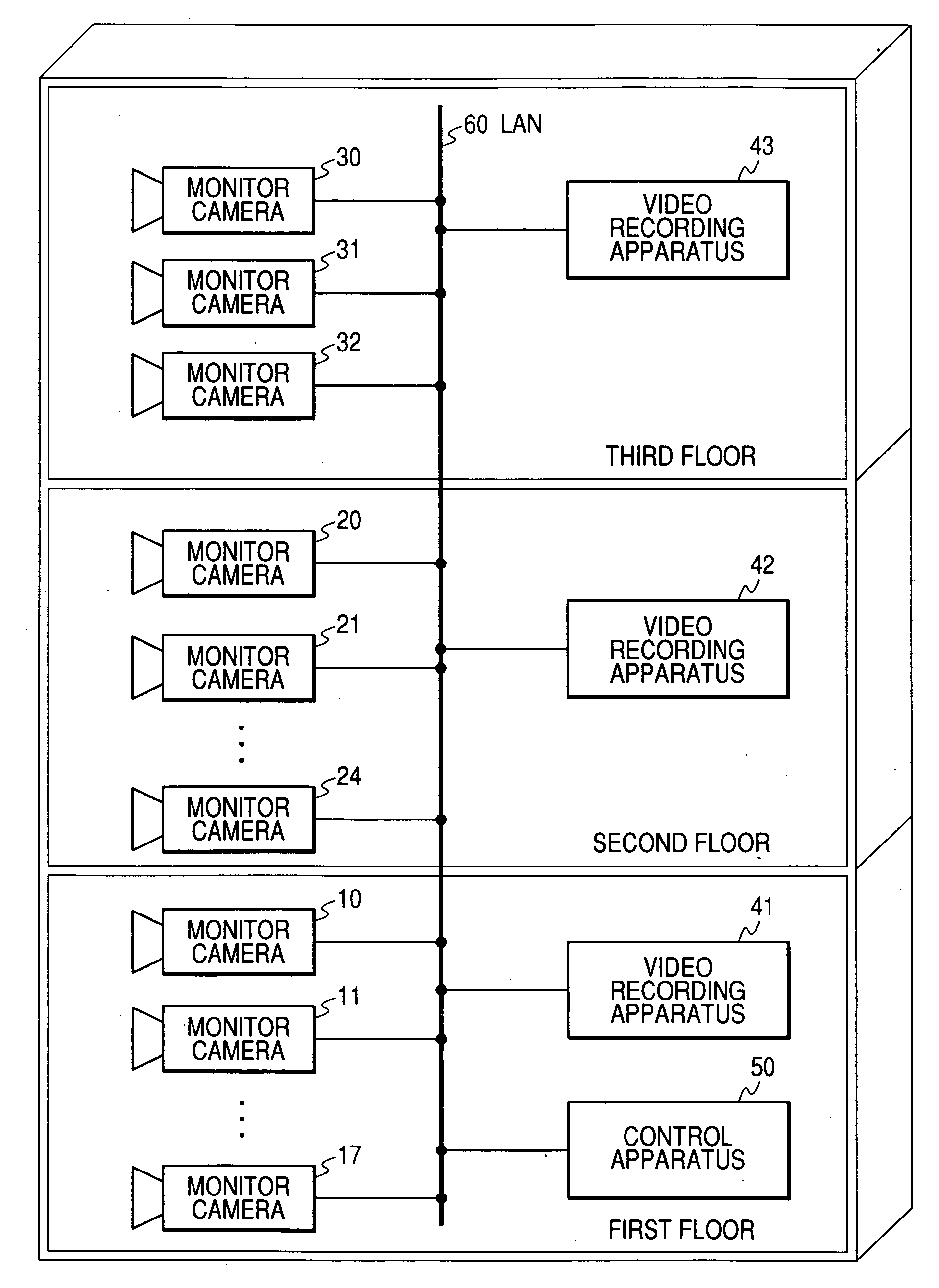
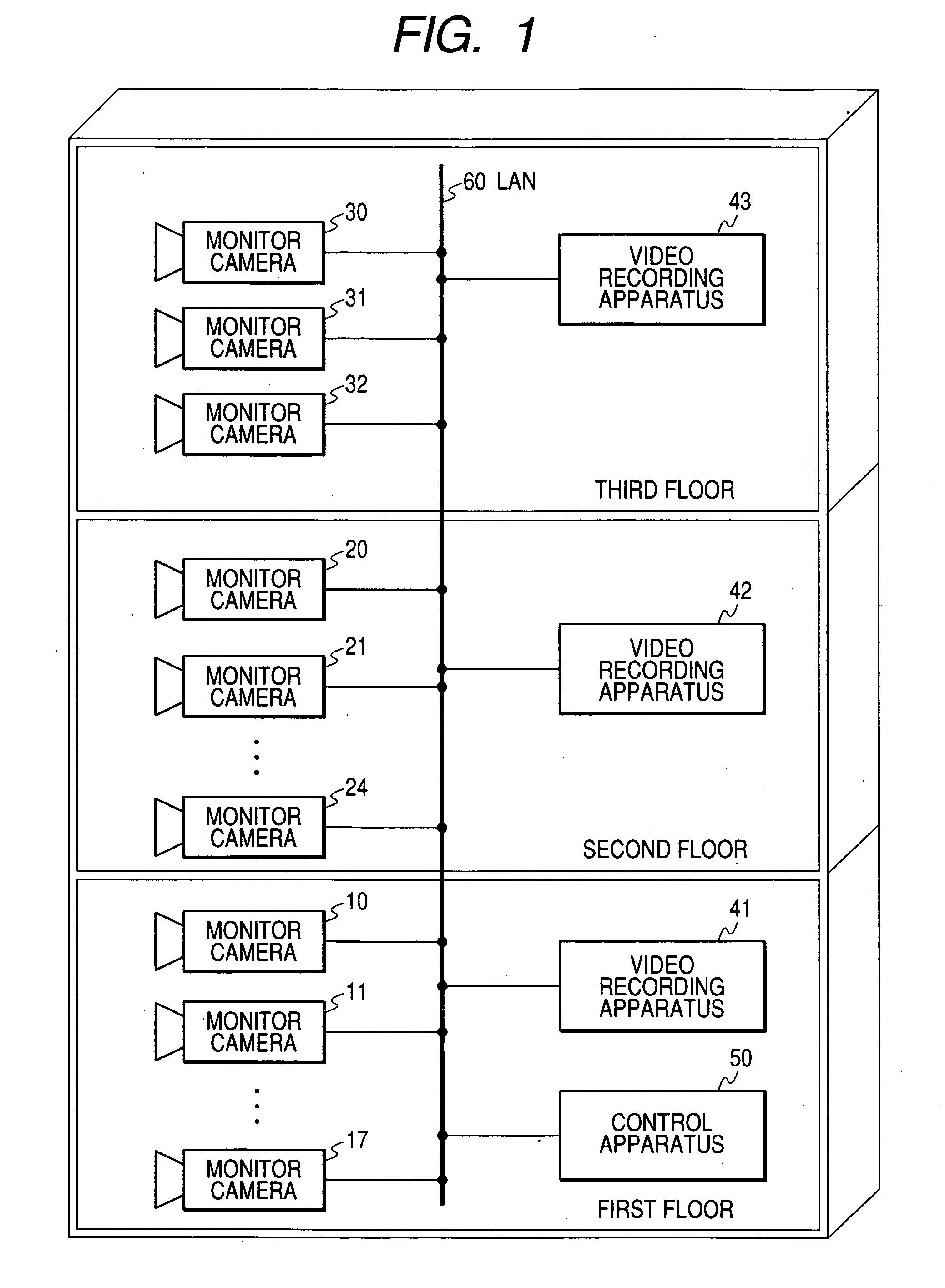
[0043]FIG. 1 shows a video recording control system according to a first embodiment of this invention. The system of FIG. 1 is provided in a building having first, second, and third floors.

[0044] The system of FIG. 1 includes monitor cameras 10, 11, . . . , 17 located at prescribed positions on the first floor of the building, monitor cameras 20, 21, . . . , 24 located at prescribed positions on the second floor of the building, and monitor cameras 30, 31, and 32 located at prescribed positions on the third floor of the building. Each of the monitor cameras 10-32 uses, for example, a general-purpose network camera.

[0045] The monitor cameras 10-32 are connected with a LAN (local area network) 60 provided in the building. Video recording apparatuses 41, 42, and 43 are located on the first, second, and third floors of the building, respectively. Each of the video recording apparatuses 41-43 includes, for example, a general-purpose network video recorder, a netw...

second embodiment

[0106] Second Embodiment

[0107] A second embodiment of this invention is similar to the first embodiment thereof except for design changes described hereafter.

[0108] According to the second embodiment of this invention, the communication interface 102 in the monitor camera 10 can receive a video request from each of the video recording apparatuses 41-43 via the LAN 60. The communication interface 102 sends the video signal to a destination identical with the video recording apparatus which makes the video request. The communication interfaces in the monitor cameras 11-32 are similar to the communication interface 102.

[0109] The communication interface 41A (the video receiver 410) in the video recording apparatus 41 can send a video request toward desired ones of the monitor cameras 10-32 via the LAN 60 while being controlled by the controller 41B. The communication interfaces in the video recording apparatuses 42 and 43 are similar to the communication interface 41A.

[0110] The vid...

third embodiment

[0113] Third Embodiment

[0114] A third embodiment of this invention is similar to the first or second embodiment thereof except for design changes described hereafter.

[0115] According to the third embodiment of this invention, the control apparatus 50 is omitted, and one of the video recording apparatus 41-43 is replaced by a video recording apparatus 80 containing a control apparatus corresponding to the control apparatus 50.

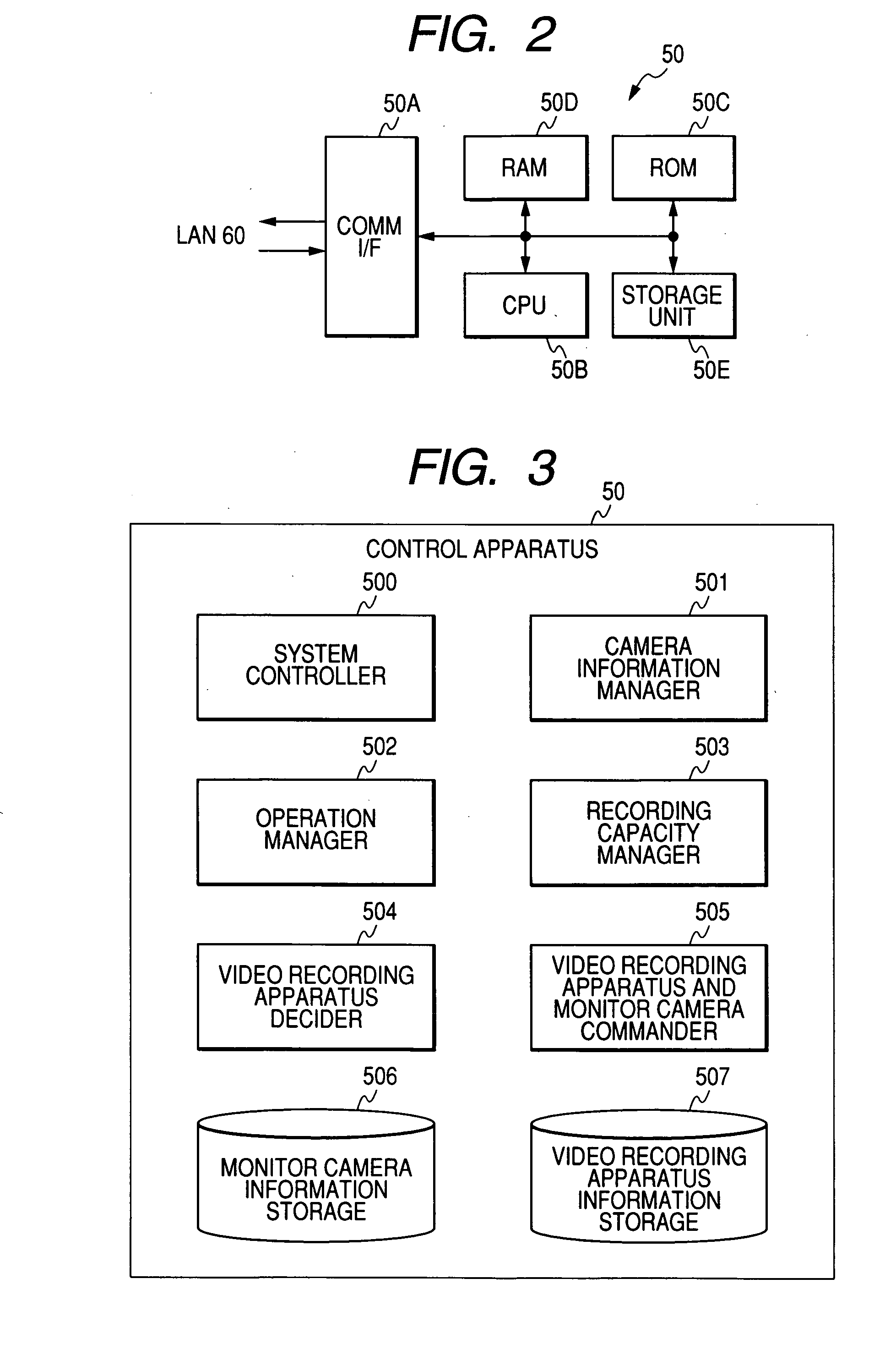
[0116]FIG. 10 shows the blocks of the functions of the video recording apparatus 80 rather than the hardware structure thereof. With reference to FIG. 10, the blocks of the functions of the video recording apparatus 80 include a system controller 800, a camera information manager 801, an operation manager 802, a recording capacity manager 803, a video recording apparatus decider 804, a video recording apparatus and monitor camera commander 805, a monitor camera information storage 806, a video recording apparatus information storage 807, a video receiver 808, ...


PUM

PropertyMeasurementUnit
transmission ratesaaaaaaaaaa
transmission rateaaaaaaaaaa
length of timeaaaaaaaaaa

Abstract

A video recording control system includes monitor cameras and video recording apparatuses. The monitor cameras are assigned to the video recording apparatuses in a manner such that each of the video recording apparatuses corresponds to at least one assigned monitor camera. Each of the monitor cameras sends its video signal to the assigned one of the video recording apparatus. The video recording apparatuses record the video signals sent from the monitor cameras. A first device operates for detecting a failure of each of the video recording apparatuses. When the first device detects a failure of at least one of the video recording apparatuses, a second device changes the assignment of the monitor cameras to the video recording apparatuses so that at least one of the monitor cameras which has been assigned to the failed video recording apparatus will be newly assigned to normal one of the video recording apparatuses.

Description

BACKGROUND OF THE INVENTION [0001] 1. Field of the Invention [0002] This invention generally relates to a video recording control system, and particularly relates to a system for controlling video cameras and video recorders connected by a network. [0003] 2. Description of the Related Art [0004] There is a monitor system including a network of cameras, displays, video recorders, and a control apparatus. It is important to previously provide the monitor system with a countermeasure for the failure of at least one of the video recorders. [0005] The video recorders have a limited recording capacity. Accordingly, to implement endless recording, each video recorder writes a new video signal portion over an old video signal portion in a recording medium. Thus, the old video signal portion is deleted from the recording medium. It is difficult to check the contents of the old video signal portion which has already been deleted from the recording medium. [0006] Japanese patent application pu...

Claims


Application Information

Patent Timeline
Patent Type & Authority Applications(United States)
IPC IPC(8): H04N5/00G11B27/00H04N5/76H04N5/765H04N7/18
CPCH04N5/247H04N5/77H04N5/781H04N5/85H04N7/181H04N9/7921H04N9/8047H04N23/90
Inventor ONODERA, KATSUYA
Owner JVC KENWOOD CORP A CORP OF JAPAN
Why Eureka
Try Eureka