Display device with improved flexibility

a technology of flexible display and display screen, which is applied in the field of flexible display screen, can solve the problems of changing the thickness of the crystal layer, the natural flexibility of the plastic substrate is not suitable, and the display utilizing glass substrates is less suitable, so as to improve flexibility and ensure the integrity of the pixels. the effect of easy manufacturing

Inactive Publication Date: 2006-09-14
EASTMAN KODAK CO
View PDF36 Cites 139 Cited by
  • Summary
  • Abstract
  • Description
  • Claims
  • Application Information

AI Technical Summary

Benefits of technology

[0010] The present invention includes several advantages, not all of which are incorporated in a single embodiment. The flexible support ensures the integrity and ease of manufacturing of the pixels by producing a stiffer substrate, while the less stiff sections allow significant bending so that the whole display can be curved into a desired form without damage to the liquid crystal. By incorporating a substrate with different materials, the present invention allows much improved flexibility. The display can be bent into a small radius without being rendered inoperable.

Problems solved by technology

Under bending moments, the rigid display tends to lose its image over a large area, due to the fact that the gap between the substrates changes, thereby causing the liquid crystal material to flow away from the bending area, resulting in a changed crystal layer thickness.
Consequently, displays utilizing glass substrates are less suitable, when a more flexible or even bendable display is desired.
However, the natural flexibility of the plastic substrate presents problems, when trying to manufacture liquid crystal displays in a traditional manner.
The flexibility of the display is limited by the bending limitation of the display enclosures.
However, the introduction of grooves to the substrate causes significant stress concentration in the grooves.
This may lead to substrate fracture during manufacturing or usage.

Method used


Image

  • Display device with improved flexibility
  • Display device with improved flexibility
  • Display device with improved flexibility

Examples


example 1

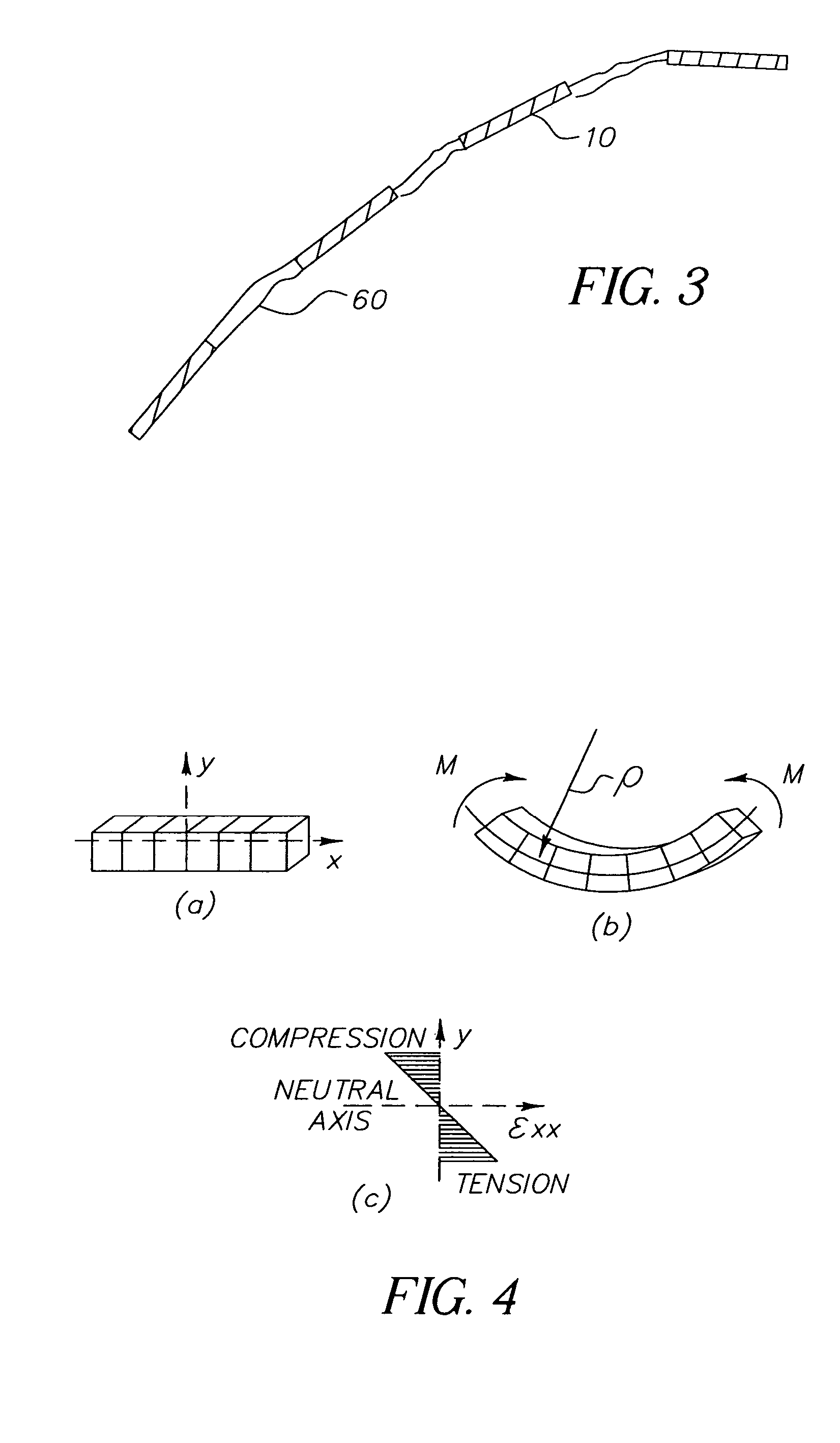
[0106] The comparative sample A in Table 1 is the prior art with no substrate area 50 (that is, the substrate area 60 covers the whole area of the substrate). Referring to Eqn. (6), the maximum strain, εmax, of the layers in the display is equal to ymaxρ,

[0107] where ρ is the bending radius of curvature and ymax is the distance from the center of the beam to the layer of concern. If the maximum strain on display module 10 is required to be less than 1%, we have, εmax=1%, and ymax=1 mm. Therefore, we have, from Eqn (6), ρ=100 mm, which, is the minimum bending radius of curvature for comparative sample A without rendering the display inoperable. Examples 1 to 4 represent displays of this invention that yield improvement of flexibility. The flexibility is measured in terms of the minimum radius of curvature of the substrate area 50 the display can be bent into without rendering inoperable. As shown in Table 1, the minimum radius of curvature of the display can be reduced by incorporat...

example 2

[0108] For the embodiment shown in FIG. 6, the improvement of flexibility can be shown in terms of the minimum radius of curvature of display in bending without rendering the display inoperable. Note that the pixel area 10 is reinforced by support reinforcement 70 and is therefore stiffer than the between-pixel area. The minimum radius of curvature of the display is defined by the radius of the curvature in the between-pixel area.

[0109] Similar to Example 1, the deformation in the display module 10 is required to be less than 1%, which yields a minimum bending radius of curvature for comparative sample B to be 100 mm. For the pixel area in FIG. 6, since there are two material layers, i.e., support 90 and support reinforcement 70, we utilize the approach outlined in “Analysis and Performance of Fiber Composites” (B. D Agarwal and L. J. Broutman, 2nd Edition, John Wiley & Sons, Inc., New York, 1990) for our calculations. We determine the radius of curvature of the between-pixel area ...


PUM

PropertyMeasurementUnit
Young's moduliaaaaaaaaaa
glass transition temperatureaaaaaaaaaa

Abstract

The present invention relates to a support for an electrically modulated imaging element and a display made with the support comprising a flexible substrate of nonhomogeneous material and of uniform thickness, which has a less flexible area underlying and more flexible area. The present invention also relates to a support for an electrically modulated imaging element and a display made with the support comprising a continuous flexible layer having attached thereto at least one reinforcing area, wherein the reinforcing area underlies an electrically modulated imaging area. The present invention also includes a method and a coextrusion die apparatus for making the support.

Description

FIELD OF THE INVENTION [0001] This invention relates in general to a display device, and more particularly to a display device comprising a stiffer support in the pixel areas to limit deformation and related failure, with less stiffness between the pixel areas to allow bending. BACKGROUND OF THE INVENTION [0002] Most of commercial displays devices, for example, liquid crystal displays, are rigid. They comprise two plane substrates, commonly fabricated by a rigid glass material, and a layer of a liquid crystal material or other imaging layer, and arranged in-between said substrates. The glass substrates are separated from each other by equally sized spacers being positioned between the substrates, thereby creating a more or less uniform gap between the substrates. Further, electrode means for creating an electric field over the liquid crystal material are provided and the substrate assembly is then placed between crossed polarizers to create a display. Thereby, optical changes in the...

Claims


Application Information

Patent Timeline
Patent Type & Authority Applications(United States)
IPC IPC(8): C09K19/00
CPCG02F1/133305G02F1/13336Y10T428/1086Y10T428/10G02F1/133377C09K2323/00C09K2323/06
Inventor GAO, ZHANJUNBOMBA, RICHARD D.
Owner EASTMAN KODAK CO
Why Eureka
Try Eureka