Exhaust gas heat exchanger

a heat exchanger and exhaust gas technology, applied in the direction of lighting and heating apparatus, machines/engines, laminated elements, etc., can solve the problems of unavoidable cost increase, inability to easily increase and the heat exchange efficiency is much higher, so as to improve reduce manufacturing costs. , the effect of improving the efficiency of heat exchang

Inactive Publication Date: 2006-09-21
DENSO CORP
View PDF10 Cites 35 Cited by
  • Summary
  • Abstract
  • Description
  • Claims
  • Application Information

AI Technical Summary

Benefits of technology

[0007] The present invention is made in view of the problems of the above conventional art, and an object of the present invention is to provide an improved exhaust gas heat exchanger. Another object of this invention is to make heat exchange efficiency much higher. A further object is to provide a compact-sized heat exchanger and to reduce manufacturing cost by adopting easy-to-assemble configuration in product designing.

Problems solved by technology

The above conventional art, however, has a problem that efficiency of heat exchange can not be easily increased due to a parallel flow, in which exhaust gas flowing inside the tubes 130 and liquid coolant flowing outside the tubes 130 (between the tubes 130) flow in the same direction.
It is another disadvantage in that the heat exchanger becomes longer in its size, because two tank portions 152 are necessary at both ends of the tubes 130 for distributing the coolant into and collecting the coolant from the multiple tubes.
Accordingly, a problem of cost increase is unavoidable due to this difficult assembling.

Method used


Image

  • Exhaust gas heat exchanger
  • Exhaust gas heat exchanger
  • Exhaust gas heat exchanger

Examples


first embodiment

(First Embodiment)

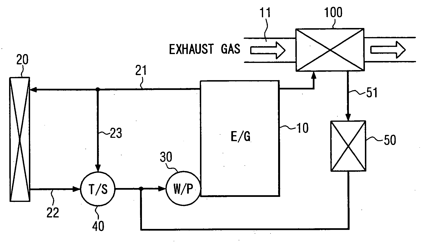
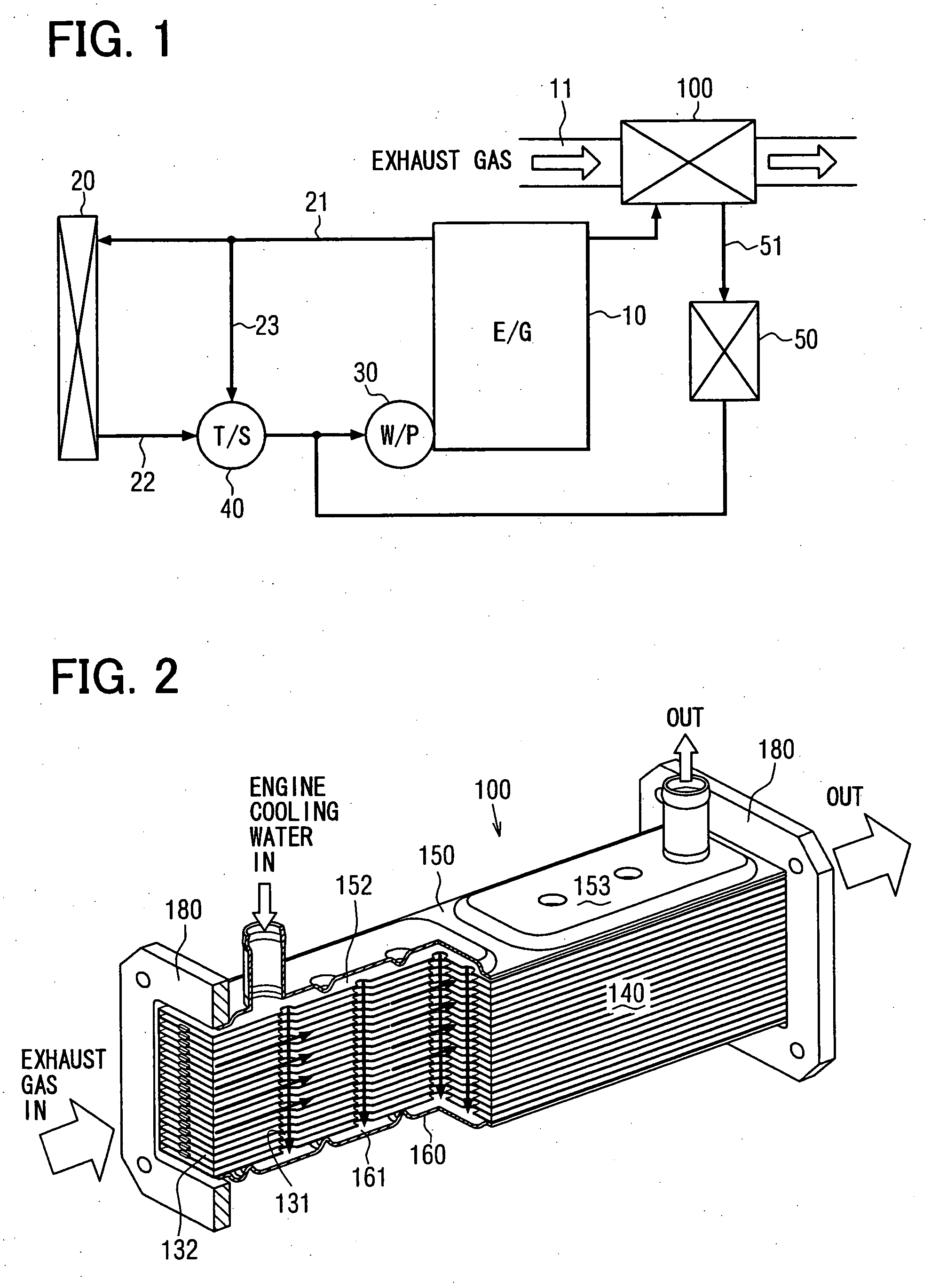
[0051] Embodiments of the present invention will be disclosed hereinafter with reference to the accompanying drawings. FIG. 1 is a schematic diagram showing a system structure of a heat exchanging apparatus for a liquid-cooled internal combustion engine. A water-cooled gasoline engine 10 used for an automotive vehicle (referred to as an engine hereinafter), as one of liquid-cooled internal combustion engines, is connected with a radiator 20 by way of an inlet pass 21 and a return pass 22, wherein the radiator carries out heat exchange between coolant (engine cooling water) for cooling the engine 10 and surrounding air.

[0052] More specifically, one side (upstream side) of the inlet pass 21 is connected with a cylinder head of the engine 10, and the other side (downstream side) thereof is connected with an inlet port of the radiator 20. One side (upstream side) of the return pass 22 is connected with an outlet port of the radiator 20, and the other side (downstream ...

first modification

(First Modification)

[0076]FIG. 8A is an oblique view of a first modification of the tube 130, and FIG. 8B is a cross sectional view taken along a line VIIIB-VIIIB in FIG. 8A. This modification differs from the first embodiment in that multiple rectangular projections (fins) 113a are formed in the tube plate 110, as shown in FIGS. 8A and 8B. With such a structure, a heat receiving area for receiving heat from the exhaust gas is increased, so that heat exchange efficiency (heating of the coolant, and cooling of the exhaust gas) between the coolant and the exhaust gas can be improved.

[0077] Since the rectangular projections 113a are integrally formed in the tube plate 110, a number of parts is not increased to thereby suppress the cost increase. The rectangular projections 113a are formed by cutting and bending respective portions of the sheet material for the tube plate 110, wherein the portions are located between the coolant flow pass holes 131a and the rectangular projections 113 ...

second modification

(Second Modification)

[0078]FIG. 9 is an oblique view of a second modification of the tube 130, which differs from the first modification in that multiple triangular projections (fins) 113b are formed in the tube plate 110. With such a structure, soot is prevented from piling up at fin portions (projections 113b) in addition to the increase of the heat exchange efficiency.


PUM


Abstract

A heat exchange core has a plurality of flat tubes laminated in a thickness direction, each flat tube defining an exhaust gas passage in which the exhaust gas flows. A plurality of coolant flow pass holes are formed in each of the flat tubes, wherein each of the coolant flow pass holes penetrates the flat tube in the thickness direction. The coolant flow pass holes of each flat tube are connected with the coolant flow pass holes of the other flat tubes, in order to respectively form a plurality of coolant flow passages through which liquid coolant flows, and the coolant flow pass holes of each coolant flow passages are communicated with each other in the laminated direction, so that the coolant flow passages are formed to be perpendicular to the exhaust gas passages.

Description

CROSS-REFERENCE TO RELATED APPLICATION [0001] This application is based on Japanese Patent Applications Nos. 2005-062803 filed on Mar. 7, 2005, and 2006-29969 filed on Feb. 7, 2006, disclosures of which are incorporated herein by reference. FIELD OF THE INVENTION [0002] The present invention relates to an exhaust gas heat exchanging apparatus for exchanging heat between exhaust gas from a liquid-cooled internal combustion engine and liquid coolant. BACKGROUND OF THE INVENTION [0003] An exhaust gas heat exchanger for performing heat exchange between exhaust gas generated by a liquid cooled internal combustion engine and liquid coolant used for cooling the engine is well known, for example, as disclosed in Japanese Patent Publication No. 2000-97578. FIG. 16 is a schematic vertical cross sectional view showing an assembly configuration of the exhaust gas heat exchanger shown in the above Japanese Patent Publication. A heat exchange core 140 has a plurality of laminated tubes 130 formin...

Claims


Application Information

Patent Timeline
Patent Type & Authority Applications(United States)
IPC IPC(8): F01N3/02F01N5/02F28D1/00F28F1/32
CPCF01N5/02F02M25/0737F28D9/0037F28D21/0003F28F1/42F28F3/044F28F3/086Y02T10/121Y02T10/16F02M26/32F28F2250/102Y02T10/12
Inventor YAMAGUCHI, HIROOYAMAGUCHI, TADAAKIYAMAGUCHI, HIDEKOSAKO, YUUJIMURAMATSU, KENSHIRO
Owner DENSO CORP
Why Eureka
Try Eureka