Coal fired gas turbine for district heating

a district heating and coal fired technology, applied in the direction of gas turbine plants, machines/engines, mechanical equipment, etc., can solve the problems of high personnel costs, high front capital investment, and appreciably delayed return on capital, and achieve low personnel costs, moderate capital costs, and short installation time

Inactive Publication Date: 2006-09-21
FIREY JOSEPH CARL
View PDF4 Cites 28 Cited by
  • Summary
  • Abstract
  • Description
  • Claims
  • Application Information

AI Technical Summary

Benefits of technology

[0010] It would be desirable to have available district heating plants which were wholly automated, and thus required very low personnel costs per unit of output, and were of moderate capital cost. In this way, small plants, with short installation time, and quick returns on capital, could be used advantageously in the United States. Very preferably, these small district heating plants are to be capable of using low cost, and readily available, coal fuel as the primary energy source.

Problems solved by technology

These prior art district heating plants, using a high pressure steam boiler, require the attendance of several qualified boiler operators, at all times, resulting in high personnel costs.
As a result, a large, up front capital investment is required, and with installation time being long, returns on this capital are appreciably delayed.

Method used


Image

  • Coal fired gas turbine for district heating
  • Coal fired gas turbine for district heating
  • Coal fired gas turbine for district heating

Examples


Embodiment Construction

A. Single Turbine Option

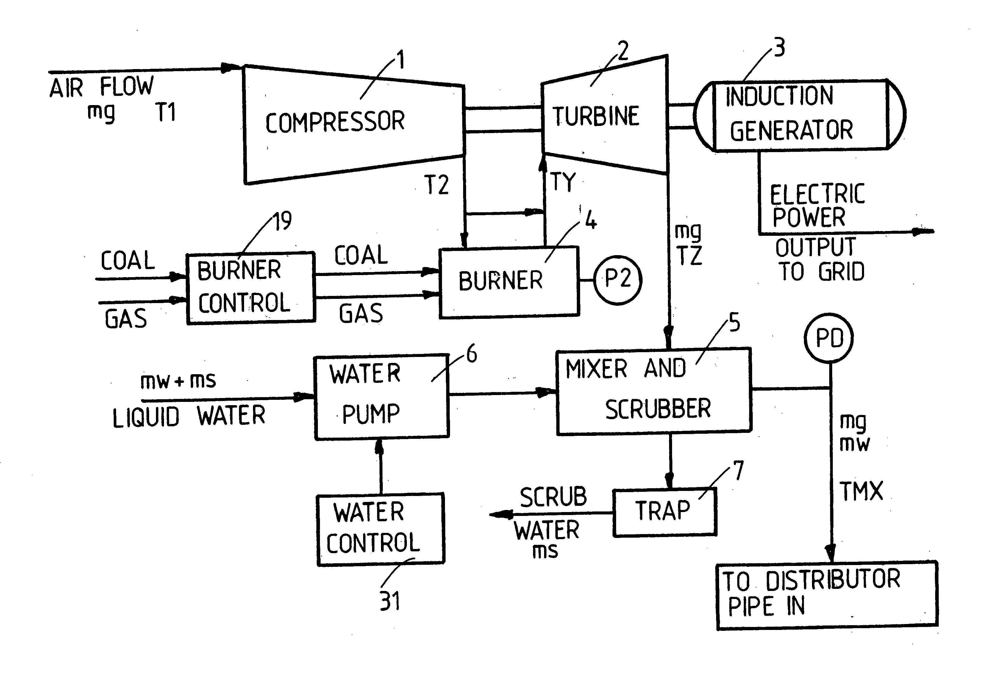
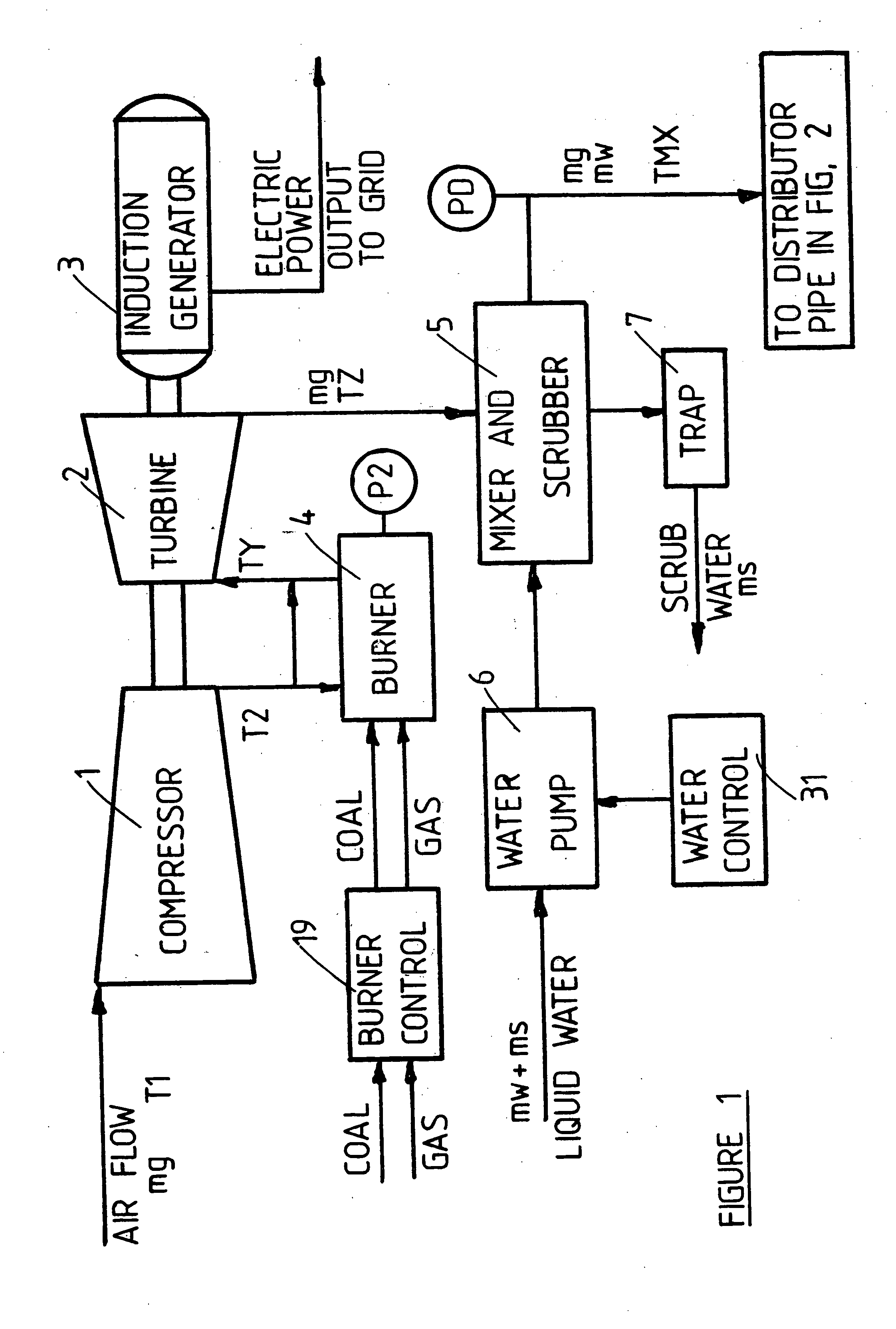
[0030] A schematic diagram of one form of coal fired gas turbine district heating system, of this invention, is shown schematically in FIG. 1, and the related FIG. 2, and comprises the following components: [0031] 1. The gas turbine engine comprises: an air compressor, 1, driven by the turbine, 2, which also drives the induction generator, 3. Air flows through, and is compressed within, the compressor, 1, and this compressor discharge air flows partially into the burner, 4, and partially bypasses the burner, in order to cool the hot burned gases leaving the burner. The burner air reacts with coal fuel, and / or natural gas fuel, within the burner, 4, and the resulting hot burned gases are mixed with the bypass air, and pass into the expander turbine, 2. This mixture of hot burned gases, and bypass air, expands through the turbine, 2, from burner pressure, P2, down to mixer and scrubber pressure, PD, performing net work as a result of the greater specific volume...


PUM


Abstract

A district heating system is described, for heating several homes and businesses in a district. The hot exhaust gas, of a gas turbine engine, is saturated with water vapor, and then passed through each home heater, where condensation of the water vapor provides heat to each home. With low cost coal fuel, burned in the gas turbine engine burner, a large portion of the fuel energy is efficiently utilized for home heating and electric power generation. In this way, low cost domestic coal can replace expensive imported petroleum fuels for home heating and electric power generation.

Description

SUMMARY OF THE INVENTION [0001] The hot exhaust gas, from a gas turbine engine, is mixed with liquid water to create a water vapor saturated gas. Within the several home heat exchangers, through which this gas is passed, the condensation of this water vapor transfers heat into the home air, and thus heats the several homes within the district. The gas turbine engine also generates electric power, and the combined heating and electric load can equal 70 to 90 percent of the fuel energy supplied to the gas turbine burner. [0002] Preferably coal is the principal fuel for the gas turbine engine burner, though other fuels can be used, alternatively, or in combination with coal. An example mixed fuel coal burner for gas turbine engines, is described in my related U.S. patent application, Ser. No. 11 / 103228. [0003] In this way very efficient fuel utilization is obtained, and low cost coal can replace expensive furnace oil, and natural gas, for home heating. Such substitution of domestic coa...

Claims


Application Information

Patent Timeline
Patent Type & Authority Applications(United States)
IPC IPC(8): F02C6/00
CPCF02C3/26F02C6/18Y02E20/14
Inventor FIREY, JOSEPH CARL
Owner FIREY JOSEPH CARL
Why Eureka
Try Eureka