Combustion chamber

a combustion chamber and chamber wall technology, applied in the field of combustion chambers, can solve the problems of damage to heat shield elements or their fastening devices, high thermal loading of components and structural members exposed to this medium, and damage to heat shield elements or even parts thereof, so as to facilitate the evaluation of output signals and monitor good effects

Inactive Publication Date: 2006-09-21
SIEMENS AG
View PDF12 Cites 11 Cited by
  • Summary
  • Abstract
  • Description
  • Claims
  • Application Information

AI Technical Summary

Benefits of technology

[0025] In order to avoid damage from heat shield elements or parts thereof which have worked loose in the area of the turbine unit of the gas turbine, the gas turbine can advantageously be switched off automatically via the evaluation circuit. In the event of the loss of a heat shield element being detected by temperature sensors or by the evaluation circuit connected downstream, then in particular the combustion chamber as well as the turbine can be brought to a stop promptly after the loss of a heat shield element.
[0026] The advantages achieved with the invention consist in particular in that loss of a heat shield element or of parts thereof is reliably detectable as a result of the positioning of temperature sensors between combustion chamber wall and heat shield elements of a combustion chamber and damage therefrom in the turbine unit connected downstream of the combustion chamber can be avoided by the gas turbine being automatically shut down in the event of the loss of a heat shield element by the evaluation circuit connected downstream of the temperature sensors. The advantage of using temperature sensors which are fashioned in particular along a run is that not every heat shield element has to be individually equipped with a temperature sensor, but a plurality of heat shield elements can be monitored by means of one temperature sensor or one measuring circuit. The use of thermocouples and in particular of a sheathed thermocouple has, in addition to providing a good facility for monitoring the heat shield elements and ease of evaluation of the output signal, the advantage that thermocouples can be used for very high temperatures and are therefore recommended for monitoring the heat shield elements in the combustion chamber wall.

Problems solved by technology

With such high temperatures of the working medium, however, the components and structural members exposed to this medium are exposed to high thermal loadings.
A problem when operating a gas turbine is the fact that heat shield elements or even parts thereof can work loose from the combustion chamber wall.
As a rule, this happens because the heat shield elements or their fastening devices are damaged by the extreme influences in the interior of the combustion chamber such as the high thermal loadings or shocks or vibrations of the combustion chamber.
These turbulences are generally so strong that moving blades such as in particular the moving blades of the first turbine stage snap off and thereby destroy large parts of the turbine unit, as well as the neighboring and adjoining rows of guide vane and moving blades.
In the event of the turbine unit being damaged, in addition to repair costs, loss-of-production costs of the gas turbine, in particular, can also accrue so that very high total costs can accrue.

Method used


Image

  • Combustion chamber
  • Combustion chamber
  • Combustion chamber

Examples


Embodiment Construction

[0033] Identical parts are labeled in all the Figures with the same reference characters.

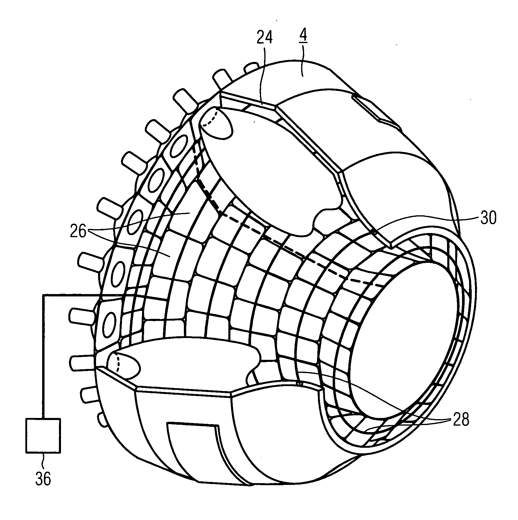
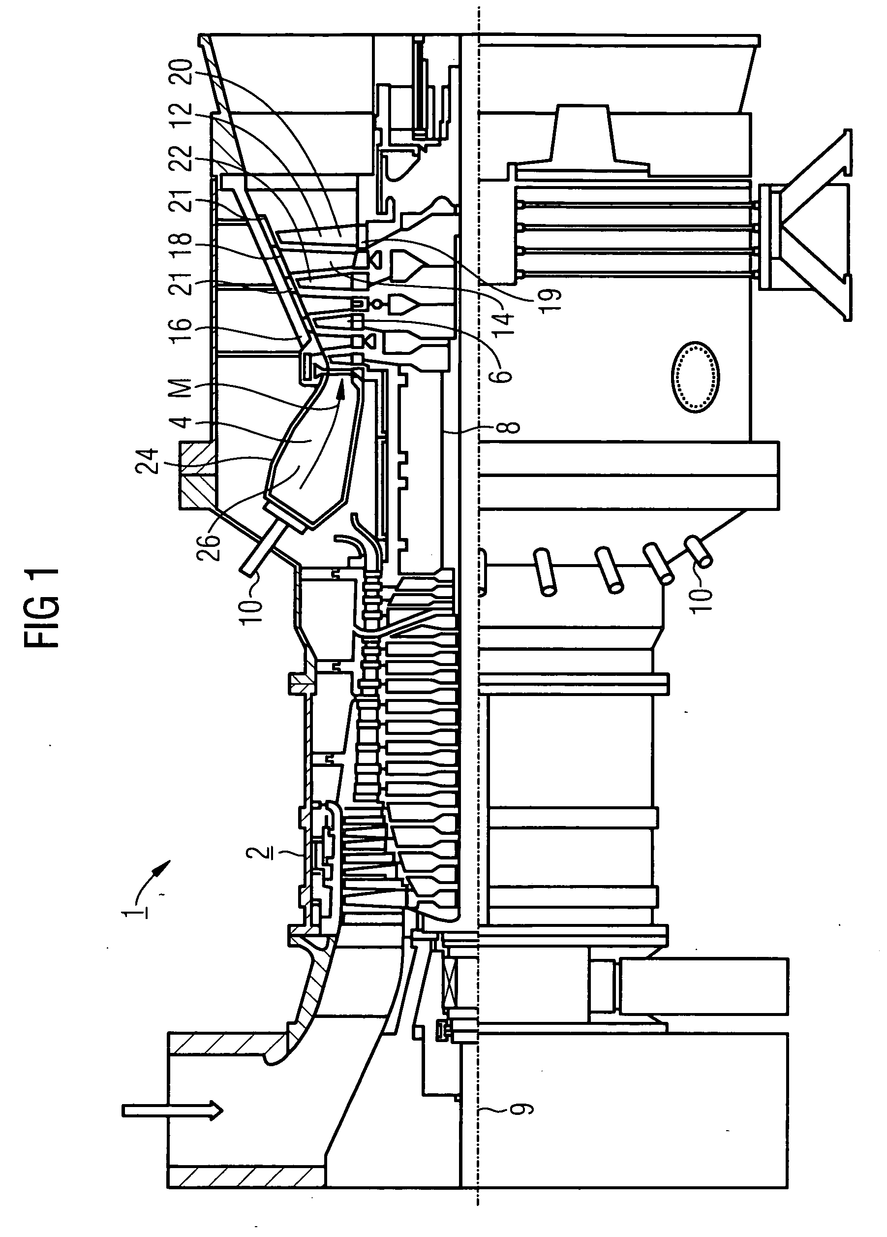
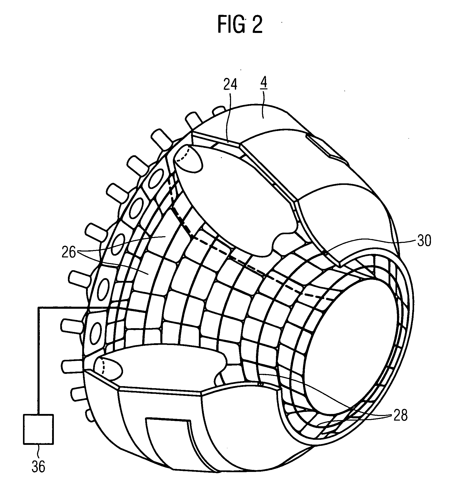
[0034] The gas turbine 1 according to FIG. 1 has a compressor 2 for combustion air, a combustion chamber 4 and a turbine 6 for driving the compressor 2 and a generator (not shown) or a machine. For this purpose, the turbine 6 and the compressor 2 are arranged on a common turbine shaft 8, also called a turbine rotor, to which the generator or the machine is also connected and which runs on bearings rotatably about its center axis 9. The combustion chamber 4, which is fashioned in the form of an annular combustion chamber, is fitted with a number of burners 10 for burning a liquid or gaseous fuel.

[0035] The turbine 6 has a number of rotatable moving blades 12 connected to the turbine shaft 8. The moving blades 12 are arranged on the turbine shaft 8 in the form of a ring and thus form a number of rows of moving blades. The turbine 6 also comprises a number of fixed guide vanes 14 which are likewi...


PUM


Abstract

A combustion chamber (4) for a gas turbine (1), the combustion chamber wall (24) of which is furnished on the inside with a lining formed of a number of heat shield elements (26), is to be designed for a particularly high level of operating safety. To this end, one or a number of temperature sensors (28) is/are located according to the invention between combustion chamber wall (24) and heat shield elements (26).

Description

CROSS REFERENCE TO RELATED APPLICATION [0001] This application is the US National Stage of International Application No. PCT / EP2004 / 003584, filed Apr. 5, 2004 and claims the benefit thereof. The International Application claims the benefits of European Patent applications No. 03009942.8 EP filed Apr. 30, 2003, all of the applications are incorporated by reference herein in their entirety.FIELD OF THE INVENTION [0002] The invention relates to a combustion chamber for a gas turbine, the combustion chamber wall of which is furnished on the inside with a lining formed of a number of heat shield elements. The invention also relates to a gas turbine with a combustion chamber of this type. BACKGROUND OF THE INVENTION [0003] Combustion chambers are among other things an integral part of gas turbines, which are used in many fields for driving generators or machines. Here, the energy content of a fuel is used for generating a rotational movement of a turbine shaft. To this end, the fuel is bu...

Claims


Application Information

Patent Timeline
Patent Type & Authority Applications(United States)
IPC IPC(8): F02C7/00F23M5/00F23N5/14F23R3/00
CPCF23M5/00F23N5/14F23N2031/10F23N2031/16F23N2041/20F23R3/002F23N2231/10F23N2231/16F23N2241/20
Inventor STOCKER, BERNDTERTILT, MARC
Owner SIEMENS AG
Why Eureka
Try Eureka