Ammunition for electrical discharge weapon

a technology of electrical discharge and ammunition, applied in the field of electric immobilization weapons, can solve the problems of human beings being disabled, shocking current arcing through the shortest available air gap, subduing the target, etc., and achieves the effects of increasing the arc track path, increasing the arc tracking path, and convenient use and storag

Active Publication Date: 2006-09-21
AXON ENTERPRISE INC +1
View PDF11 Cites 47 Cited by
  • Summary
  • Abstract
  • Description
  • Claims
  • Application Information

AI Technical Summary

Benefits of technology

[0007] The present invention is directed to an improved primer fired ammunition cartridge for an electrical discharge weapon which allows for a longer arc path at the target by lengthening potential arc paths across the exterior surfaces of the ammunition cartridge, while still maintaining a cartridge that is conveniently small for use and storage. The improved ammunition cartridge includes electrical contacts positioned on opposed side surfaces of a substantially rectangular housing. Ideally, each contact can be positioned approximately half way between the front and rear surfaces of the housing to avoid arc breakdowns between an exposed contact and a stored conductor. The conductor is then routed from one contact to about the nearest point of the portion of the primer case exposed on the exterior rear surface of the housing.
[0008] A plate covers the rear surface opposing the front surface. The plate does not have an aperture either over or about the primer. The plate surface facing the primer includes ridges or other areas of relief or bends to increase the arc tracking path, and is cemented to the rear surface with an epoxy or ABS cement having a dielectric strength of about 500 to 800 volts per mil. A plug raised on the plate surface seats over and secures the primer which is recessed into the housing to increase the arc track path. The plug also prevents blowback which is a loss of propulsive forces as gas escapes from the back of the primer after detonation. Contact probes extend in the cartridge to the front surface to be used as back up if the cartridge firing should fail to subdue a violent suspect.
[0009] A primer fired cartridge also can contain a recess or aperature in a flanged portion to absorb energy to reduce damage to the receiver port in the weapon. A rod also can be positioned in the receiver port to engage the aperature in the flange to prevent the cartridge from being ejected out of the weapon

Problems solved by technology

Human beings can be disabled by shocks of much lower voltage, however, the higher voltage is needed to ionize air paths, so electrical currents can penetrate otherwise insulated garments worn by the human target to complete the shocking circuit through the body.
A problem with primer fired ammunition cartridges is that the shocking current will arc through the shortest available air gap.
If the distance between the target's clothing is greater than this distance, the shocking current will not arc through the target, and therefore, the darts will not subdue the target.
Additionally, the circuit might arc even a shorter distance at the target because of the phenomenon known as arc tracking, particularly if prior usage of the weapon has fouled the ammunition chamber with conductive carbon residues.
A second problem associated with previous primer fired ammunition cartridges is that over a period of time the receiving port of the weapon can become damaged due to the explosive forces of firing the ammunition.
With time and exposure to the elements, the structural integrity of the weapon can become compromised, and as the sides of the cartridges cantilever repeatedly strikes against the corresponding wall of the seating depression in the wall of the receiver port, the receiver's plastic can fracture and chip off.
If enough plastic dislodges from the wall, resultant forces might fire the entire cartridge out of the weapon after the cartridge's charge is detonated.

Method used


Image

  • Ammunition for electrical discharge weapon
  • Ammunition for electrical discharge weapon
  • Ammunition for electrical discharge weapon

Examples


Embodiment Construction

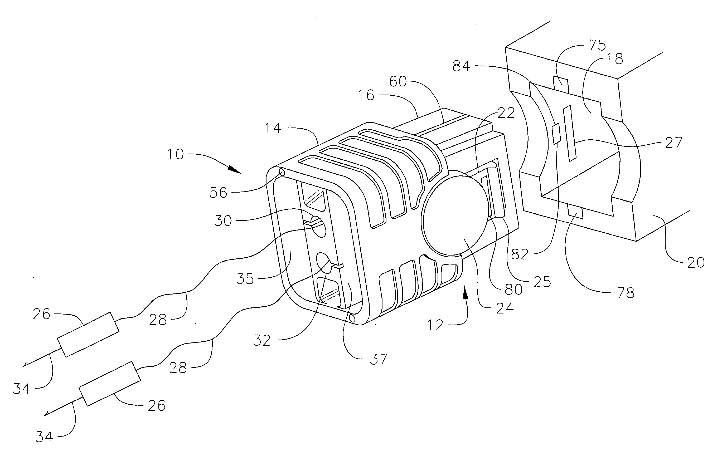
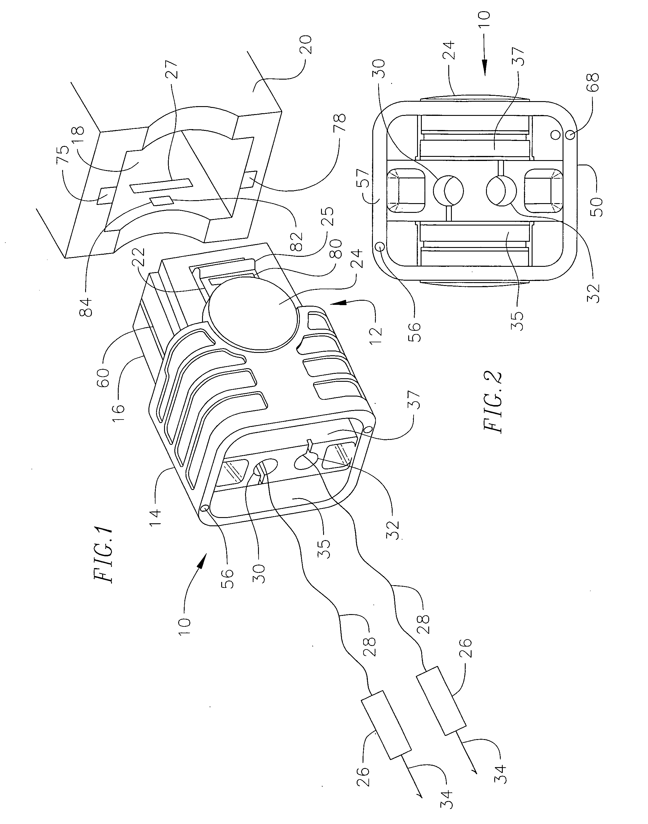
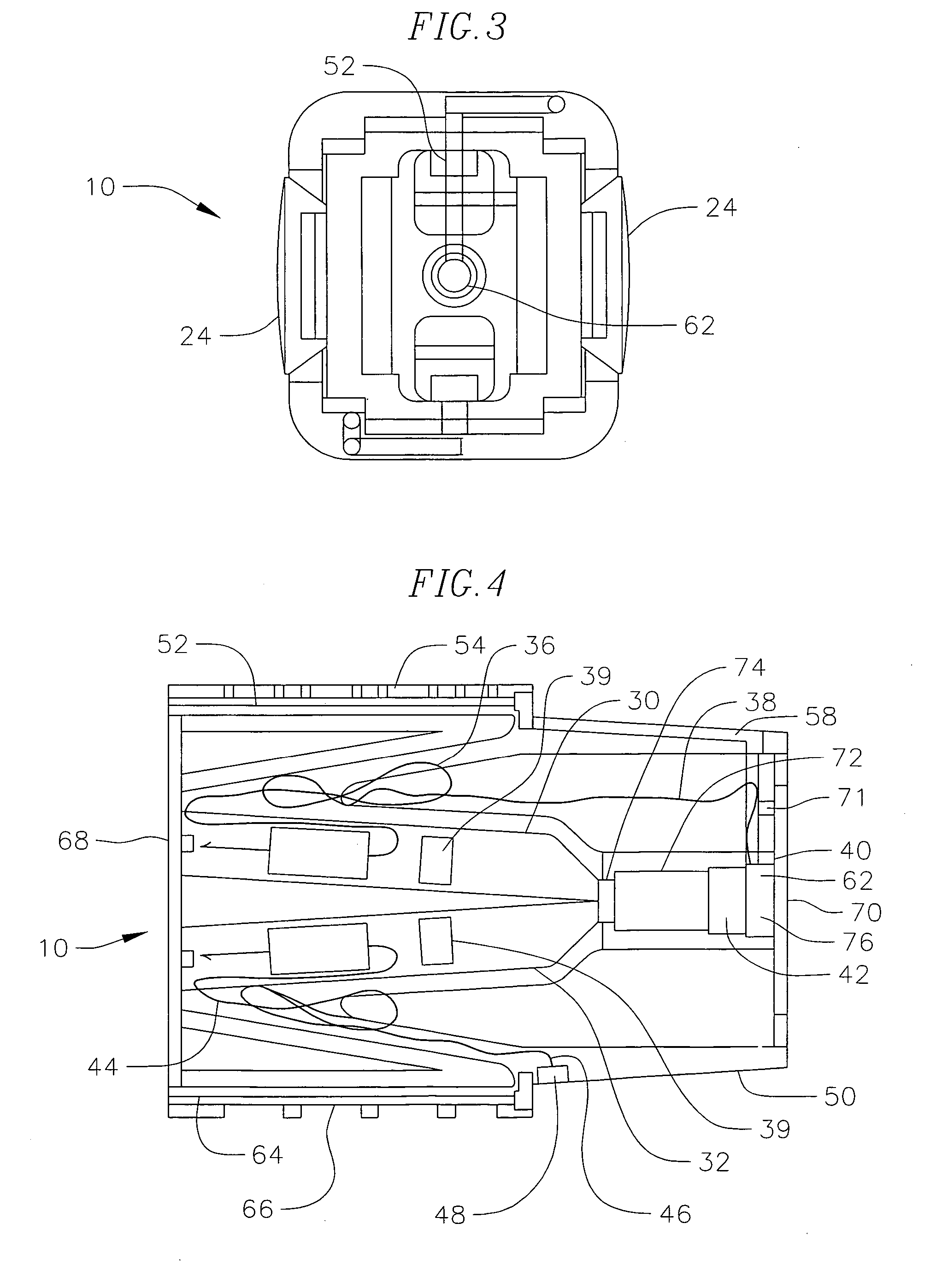
[0014] Referring to FIGS. 1 through 4, an ammunition cartridge 10 of the present invention is illustrated. The cartridge has a housing 12 formed of high impact plastic having a forward section 14, and a rear section 16. Rear section 16 is received within a cavity or receiver port 18 of an electrical discharge weapon 20. Flexible flanges 22 extend along each side of the housing, and include a boss 24 to flex the flange during insertion and removal of the cartridge from the cavity 18. The flange includes a raised stop 25 for receipt into a recess 27 in port 18 to retain the cartridge in the weapon. Dart 26 and wire assemblies 28 are positioned within dart chambers 30 and 32 contained within the housing 12. Dart chambers 30 and 32 extend into the housing at an angle so that the darts when propelled from the housing separate from one another in flight. Darts 26 each include a barbed hook 34. The wire assemblies 28 include a span of insulated conductor which is wound 36 and positioned wi...


PUM


Abstract

A primer-fired ammunition cartridge for an electrical discharge weapon having a housing with an exterior surface and two wire-tethered darts positioned within dart chambers in the housing and two electrical contacts positioned on opposite surfaces of the housing for lengthening an electrical arc path across the exterior surface of the housing. The housing can include a flange portion for engaging a chamber in an electrical discharge weapon wherein the flange portion includes an aperture thereby allowing the flange portion to bow and absorb resultant forces between the ammunition cartridge and the chamber of the electrical discharge weapon during firing of the cartridge.

Description

BACKGROUND OF THE INVENTION [0001] The present invention relates generally to the field of electrical immobilization weapons of the type which impart an electrical impulse to immobilize a human target by inducing involuntary muscular contractions, and more particularly, to an improved ammunition cartridge for the electrical discharge weapon which provides for a longer arc path at the target by lengthening potential arc paths across the exterior surfaces of the ammunition cartridge, while still maintaining a conveniently small size for use and storage. Electrical discharge weapons, commonly sold under the trademark TASER, are weapons that connect a human target to a remote electrical power supply by means of a pair of darts and trailing conductors, so that the human target can be disabled by an electrical shock from the weapon. The typical power supply of an electrical discharge weapon produces low amperage shocks of 50 KV. Human beings can be disabled by shocks of much lower voltage...

Claims


Application Information

Patent Timeline
Patent Type & Authority Applications(United States)
IPC IPC(8): F41C9/00H01T23/00
CPCF41H13/0025F42B12/36H05C1/06
Inventor MCNULTY, JAMES F.HULTMAN, JOHN A.
Owner AXON ENTERPRISE INC
Why Eureka
Try Eureka