Glow plug energization control to avoid overheating

a technology of energizing control and glow plug, which is applied in the direction of mechanical equipment, light and heating equipment, machines/engines, etc., can solve the problems of over-the-top glow plug energizing control system, increase in physical load on the glow plug, and wire breakage in the glow plug, so as to avoid overheating of the glow plug, ensure the stability of energizing, and simple and inexpensive structure

Inactive Publication Date: 2006-09-21
DENSO CORP
View PDF6 Cites 18 Cited by
  • Summary
  • Abstract
  • Description
  • Claims
  • Application Information

AI Technical Summary

Benefits of technology

[0012] It is another object of the invention to provide a simple and inexpensive structure of a glow plug energization control apparatus designed to ensure the stability in energizing a glow plug which is installed in, for example, a diesel engine.
[0013] According to one aspect of the invention, there is provided a glow plug energization controlling apparatus which may be employed in diesel automotive vehicle. The apparatus comprises: (a) a power supply working to supply electric power to a glow plug mounted in an internal combustion engine; (b) an on-off switch working to produce a control trigger signal when turned on; and (c) a controller including a microcomputer. The controller is responsive to the control trigger signal to control supply of the electric power from the power supply to energize the glow plug. The microcomputer works to monitor an off-on interval from turning off to turning on of the on-off switch and control an amount of energization of the glow plug as a function of the off-on interval, thereby avoiding overheating of the glow plug.
[0014] In the preferred mode of the invention, the microcomputer also monitors an switch on-duration for which the on-off switch is in an on-state and controls the amount of energization of the glow plug as a function of the switch on-duration.

Problems solved by technology

Rough control of an on-duration for which the dc voltage is applied to the glow plug will, thus, result in increase in physical load on the glow plug.
For instance, too long the on-duration of the glow plug will result in overheating of the glow plug, which may lead to wire breakage in the glow plug.
The above glow plug energization control systems, however, encounter a drawback in the following situation.
When the glow plug continues to be energized over the initial energization duration and the temperature-holding time, it may cause the glow plug to overheat.
This system, however, requires an electrical circuit which measures the voltage and current given to the glow plug to determine the optimum amount of energization, thus resulting in complexity and increase in production cost of the system.

Method used


Image

  • Glow plug energization control to avoid overheating
  • Glow plug energization control to avoid overheating
  • Glow plug energization control to avoid overheating

Examples


Embodiment Construction

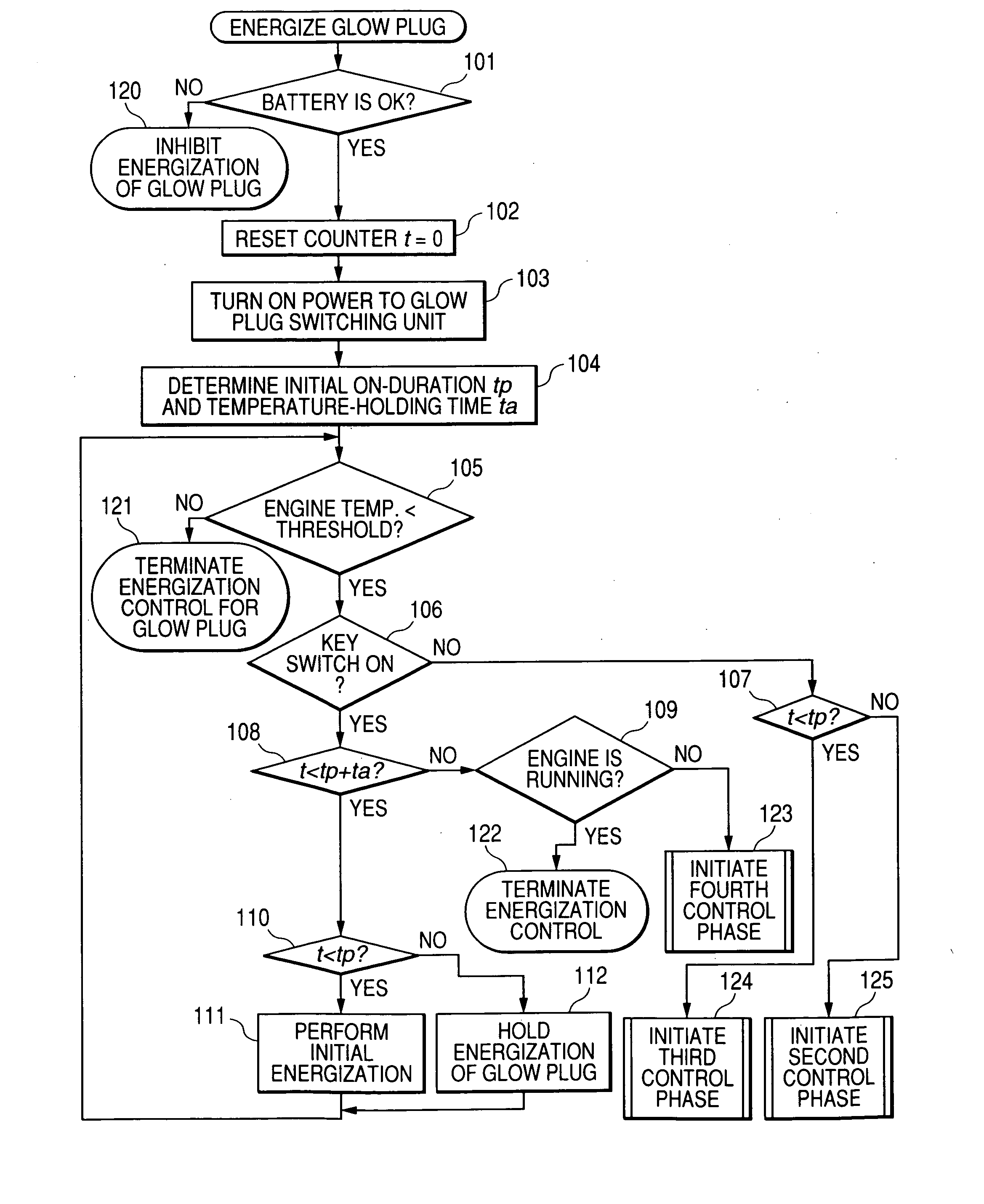
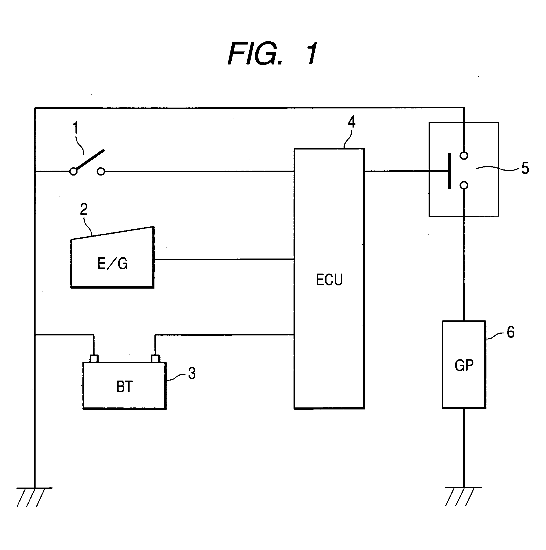
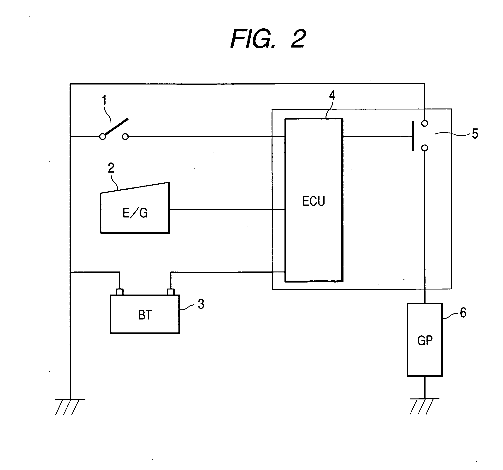
[0041] Referring to the drawings, wherein like reference numbers refer to like parts in several views, particularly to FIG. 1, there is shown a glow plug controller according to the invention.

[0042] The glow plug controller is mainly constructed by an engine electronic control unit (ECU) 4 equipped with a microcomputer usually installed in an automotive vehicle. The glow plug controller includes a glow plug on-off switching unit 5 equipped with a switch leading to a glow plug 6 installed in a diesel engine 2. The engine ECU 4 is connected to a storage battery 3 and a key switch 1 implemented by an on-off switch such as a typical automotive ignition switch. The glow plug on-off switching unit 5 is so controlled by the ECU 4 that it is opened and closed cyclically for a short period of time and preferably implemented by an electronic switch such as a transistor, a power MOSFET, or a thyristor or a switching circuit including them.

[0043] The engine ECU 4 monitors the voltage, as deve...


PUM


Abstract

A glow plug energization control apparatus is provided which includes a power supply working to supply electric power to a glow plug mounted in an internal combustion engine, an on-off switch working to produce a control trigger signal when turned on, and a controller including a microcomputer. The microcomputer is responsive to the control trigger signal to control supply of the electric power from the power supply to energize the glow plug. The microcomputer works to monitor an off-on interval from turning off to turning on of the on-off switch and control an amount of energization of the glow plug as a function of the off-on interval, thereby avoiding overheating of the glow plug.

Description

CROSS REFERENCE TO RELATED DOCUMENT [0001] The present application claims the benefit of Japanese Patent Application No. 2005-76880 filed on Mar. 17, 2005, the disclosure of which is incorporated herein by reference. BACKGROUND OF THE INVENTION [0002] 1 Technical Field of the Invention [0003] The present invention relates generally to a glow plug energization controlling apparatus which may be employed in automotive vehicle to control energization of a glow plug working to assist in starting an internal combustion engine, and more particularly to such an apparatus equipped with a microcomputer designed to control an operation of a glow plug for avoiding overheating thereof. [0004] 2 Background Art [0005] Usually, typical diesel automotive vehicles are equipped with a glow plug working to assist in heating inside a cylinder of a diesel engine up to an ignition temperature of an air-fuel mixture, especially when the outside air temperature is low, and the engine is cold. [0006] In rec...

Claims


Application Information

Patent Timeline
Patent Type & Authority Applications(United States)
IPC IPC(8): F02P19/02
CPCF02D2200/503F02P19/022
Inventor HIRAMATSU, HIROMI
Owner DENSO CORP
Why Eureka
Try Eureka