Laser material micromachining with green femtosecond pulses

Inactive Publication Date: 2006-09-21
IMRA AMERICA
View PDF13 Cites 96 Cited by
  • Summary
  • Abstract
  • Description
  • Claims
  • Application Information

AI Technical Summary

Problems solved by technology

However, when more than a single laser pulse is used, residual heat can accumulate in the bulk of the remaining material as successive pulses are incident upon the material.
If the laser pulse repetition rate i

Method used


Image

  • Laser material micromachining with green femtosecond pulses
  • Laser material micromachining with green femtosecond pulses
  • Laser material micromachining with green femtosecond pulses

Examples


Embodiment Construction

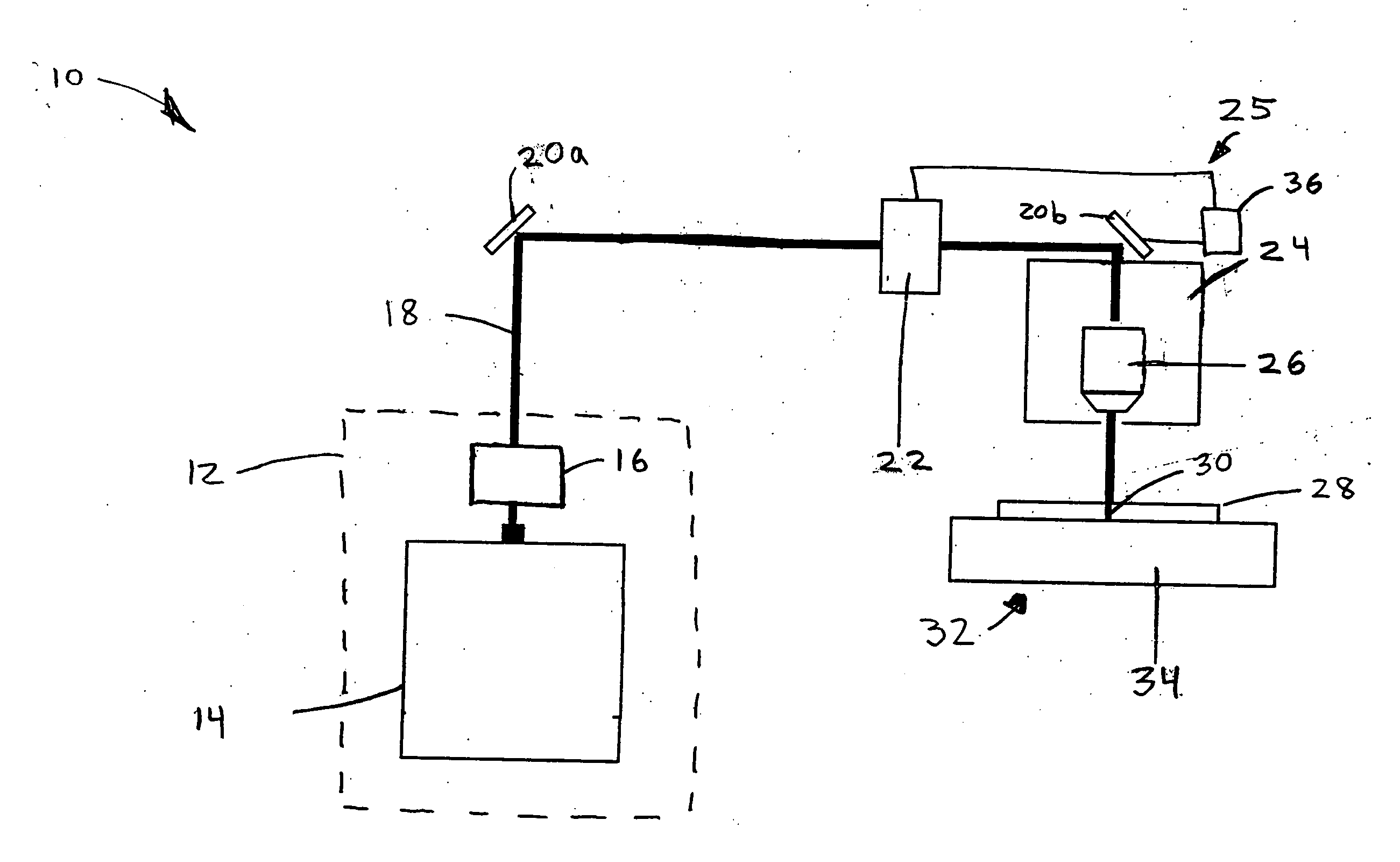
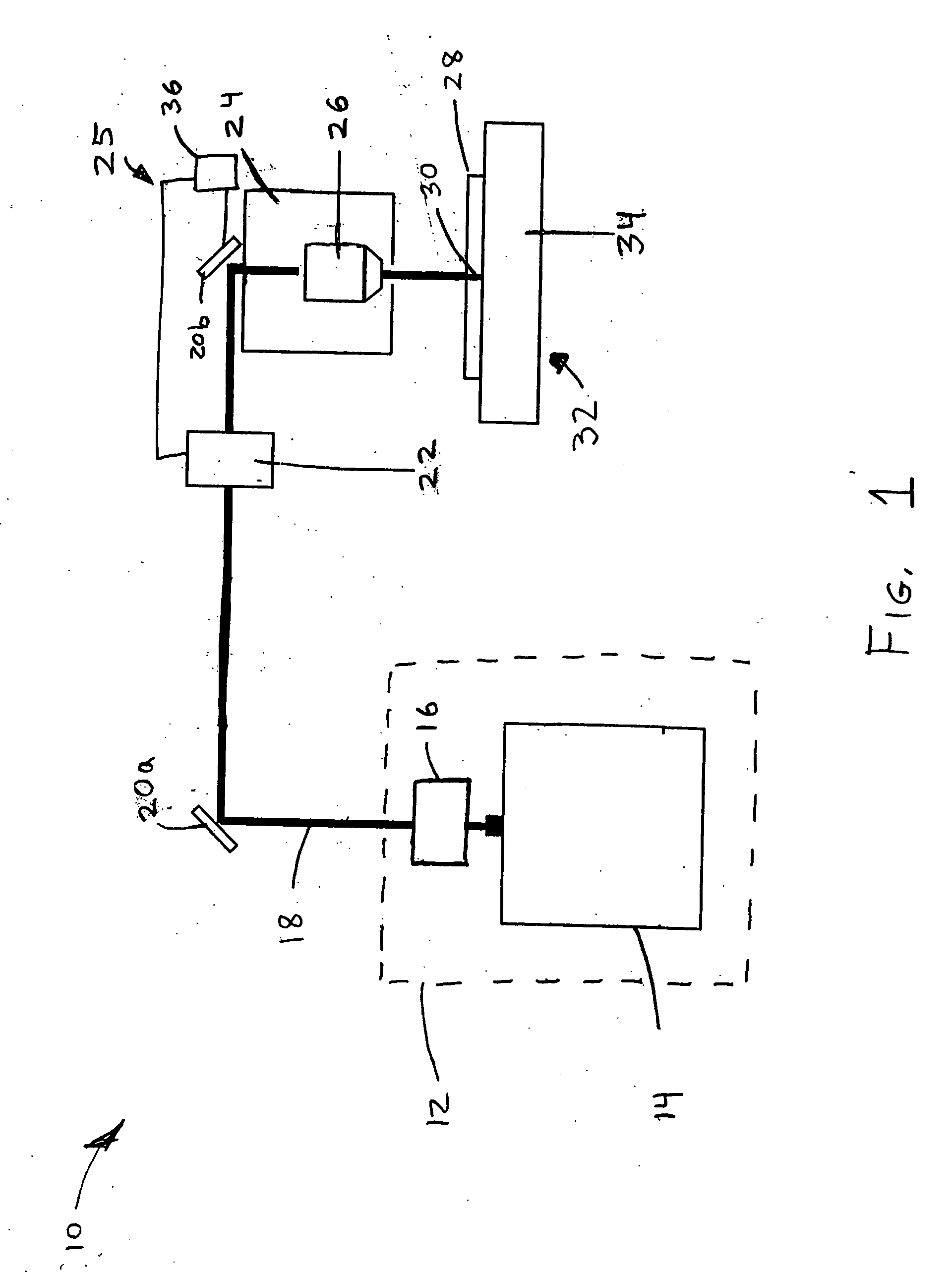
[0023] A system 10 configured to micromachine a material is shown in FIG. 1. This system 10 comprises a visible laser light source 12 that outputs visible light. The visible laser light source 12 has an output wavelength in the green region of the visible optical spectrum, e.g., between about 500 and 550 nanometers. This wavelength range may also be between about 450 and 700 nanometers in some embodiments.

[0024] The visible laser light source 12 comprises a laser configured to produce ultrashort pulses having pulse durations from about 100 fs to 20 ps. In one embodiment, the laser light source 12 comprises a Yb-doped fiber laser 14 that outputs light having a wavelength of approximately 1045 nanometers. An example Yb-doped, amplified fiber laser 14 comprises the FCPA μJewel available from IMRA America, Ann Arbor Mich. This fiber laser has a pulse repetition rate between about 100 kHz and 5 MHz and is capable of outputting ultrashort pulses having pulse durations between about 200 a...


PUM

PropertyMeasurementUnit
Timeaaaaaaaaaa
Timeaaaaaaaaaa
Timeaaaaaaaaaa

Abstract

Various embodiments of a system described herein relate to micromachining materials using ultrashort visible laser pulses. The ultrashort laser pulses may be green and have a wavelength between about 500 to 550 nanometers in some embodiments. Additionally, the pulses may have a pulse duration of less than one picosecond in certain embodiments.

Description

PRIORITY APPLICATION [0001] This application claims priority to U.S. Patent Application No. 60 / 646,101 filed Jan. 21, 2005, entitled “LASER MATERIAL MICROPROCESSING WITH GREEN FEMTOSECOND PULSES,” (Attorney Docket No. IMRAA.033PR), which is hereby incorporated by reference herein in its entirety.BACKGROUND [0002] 1. Field of the Invention [0003] The apparatus and methods relate to pulsed lasers and to micromachining with pulsed lasers. [0004] 2. Description of the Related Art [0005] Many materials can be micromachined using lasers and in particular pulsed lasers. In a laser micromachining process, laser energy is directed into a medium so as to alter the physical or structural characteristics of the medium. Typically, a portion of the irradiated material is removed, for example, by ablation. Laser micromachining can be used, for example, to drill, cut, scribe, and mill materials so as to form structures including, for example, channels, grooves, or holes, or to form other features i...

Claims


Application Information

Patent Timeline
IPC IPC(8): B23K26/38B23K26/06
CPCB23K26/0024B23K26/0036B23K26/0039B23K26/0635B23K26/367B23K26/4065B23K26/4075B23K26/409C03B33/0222H01S3/0057B23K26/0006B23K26/40B23K26/0624B23K26/364B23K2103/172B23K2103/30B23K2103/42B23K2103/50
Inventor BOVATSEK, JAMES M.ARAI, ALAN Y.SHAH, LAWRENCEYOSHINO, FUMIYO
Owner IMRA AMERICA
Why Eureka
Try Eureka