Electrostatic micro switch, production method thereof, and apparatus provided with electrostatic micro switch

Inactive Publication Date: 2006-09-21
ORMON CORP
View PDF6 Cites 54 Cited by
  • Summary
  • Abstract
  • Description
  • Claims
  • Application Information

AI Technical Summary

Benefits of technology

[0031] An embodiment of the present invention, the high resistivity is not lower than 800 Ωcm.
[0032] An embodiment of the present invention, the low resistivity is not more than 300 Ωcm.
[0033] In accordance with one aspect of the present invention, a radio communication device comprises an antenna; an internal processing circuit; and an electrostatic micro switch which is connected between the antenna and the internal processing circuit, the electrostatic micro switch comprising a fixed electrode which is provided in a fixed substrate; a movable substrate which includes a movable electrode, the movable electrode being arranged while facing the fixed electrode, the movable substrate being elastically supported by the fixed substrate; a fixed-side signal conducting unit which is provided in the fixed substrate; and a movable-side signal conducting unit which provided in the movable substrate, the movable-side signal conducting unit displacing the movable substrate by electrostatic attraction between the movable electrode and the fixed electrode to perform switching between the movable-side signal conducting unit and the fixed-side signal conducting unit, wherein the movable substrate is made of a semiconductor including a plurality of regions having different values of resistivity; at least a portion where the movable-side signal conducting un

Problems solved by technology

There are the following problems in the conventional electrostatic micro switch.
Therefore, the charging time

Method used


Image

  • Electrostatic micro switch, production method thereof, and apparatus provided with electrostatic micro switch
  • Electrostatic micro switch, production method thereof, and apparatus provided with electrostatic micro switch
  • Electrostatic micro switch, production method thereof, and apparatus provided with electrostatic micro switch

Examples


Example

(First Embodiment)

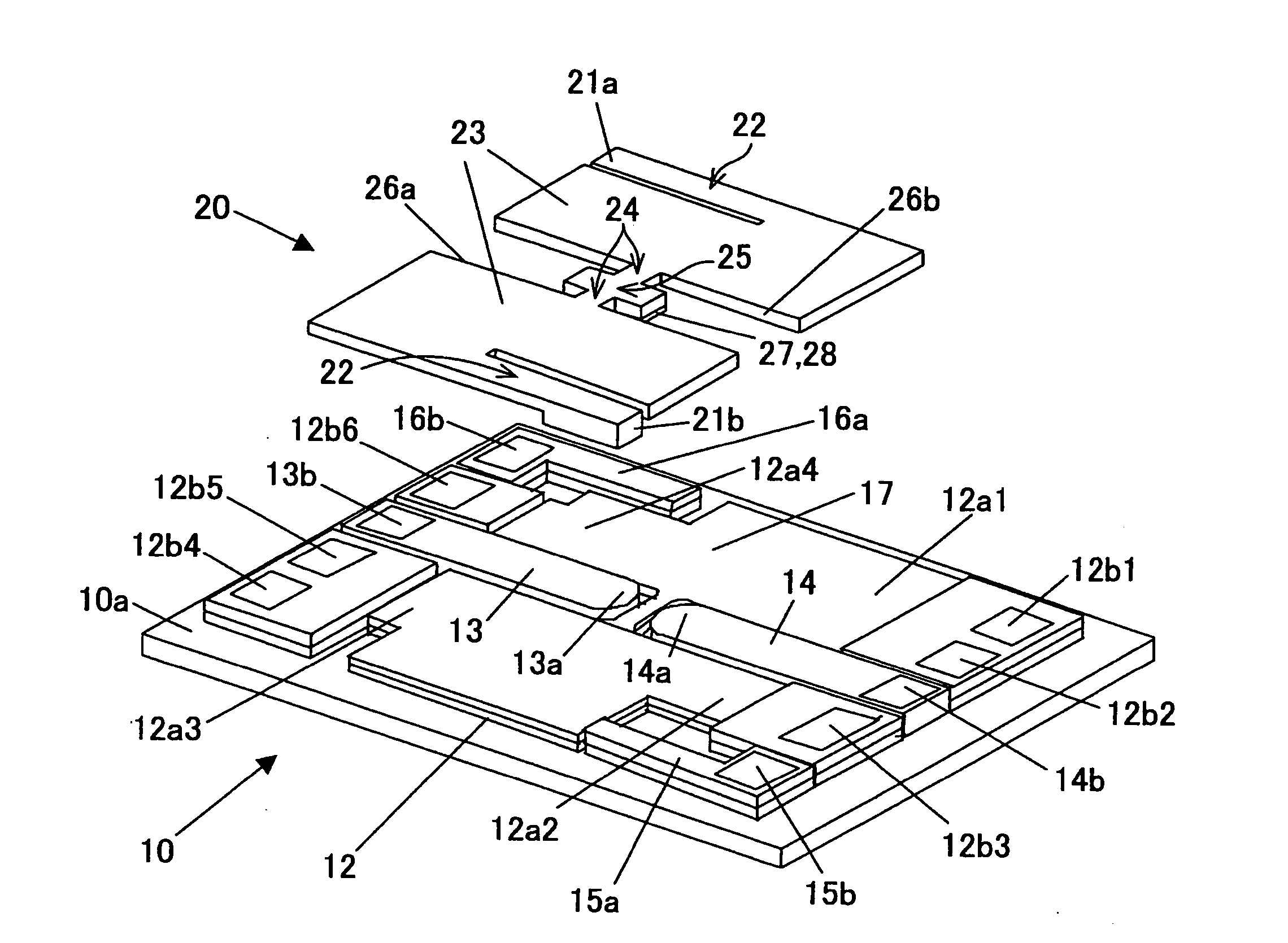
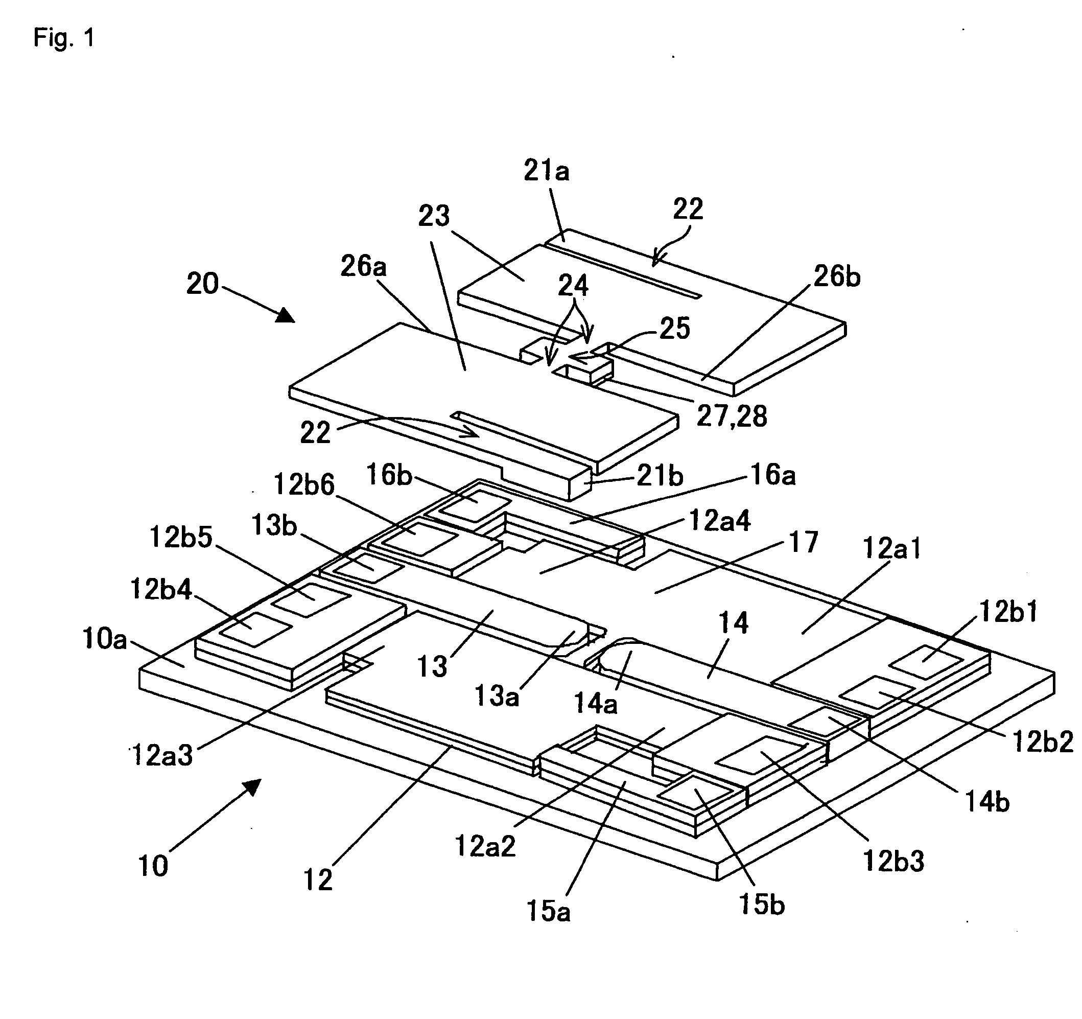
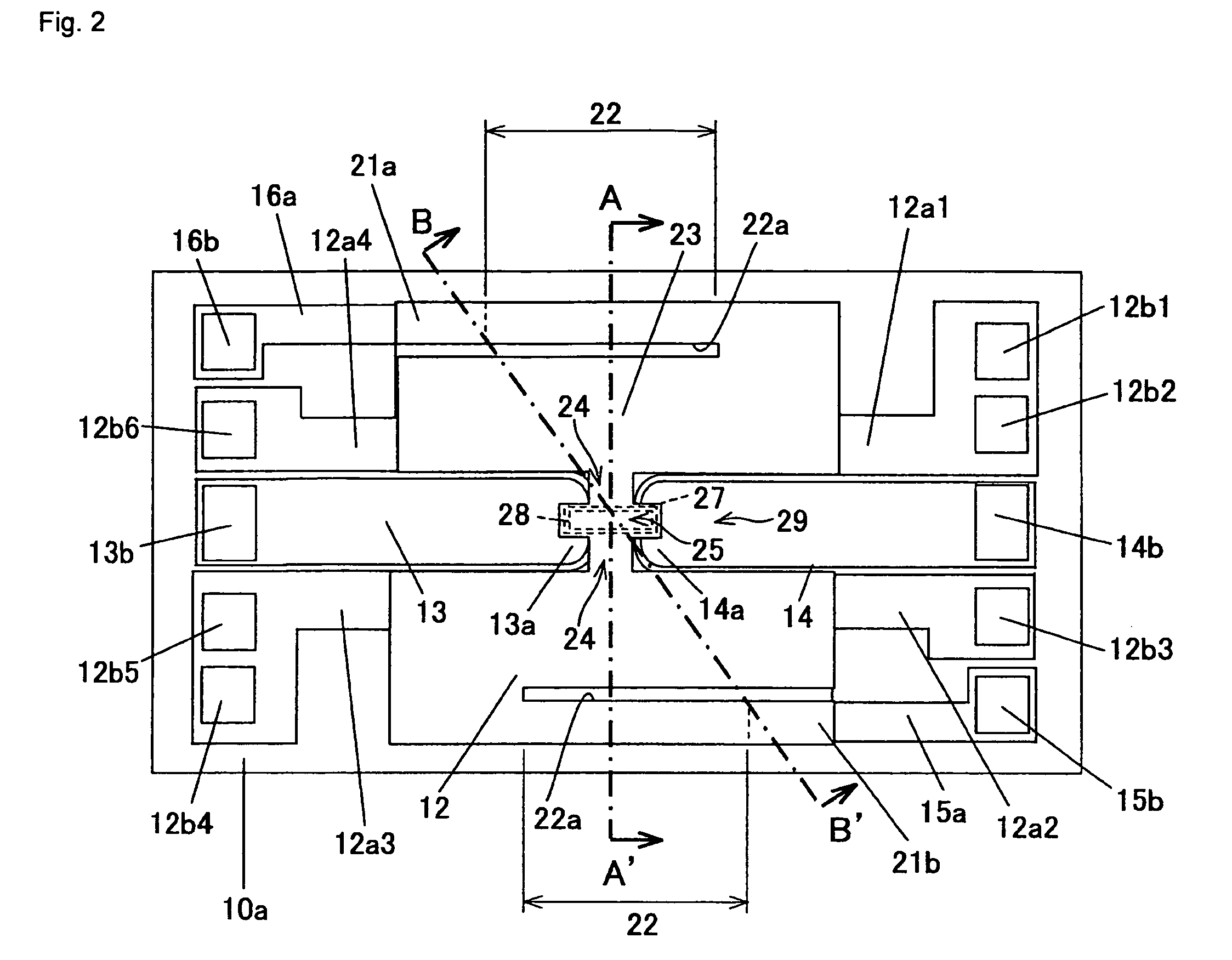
[0063] A first embodiment of the invention will be described below with reference to FIGS. 1 to 13. FIGS. 1 to 3 show a structure of an electrostatic micro switch according to the first embodiment. FIG. 1 is an exploded view showing the structure of an electrostatic micro switch of the first embodiment, FIG. 2 shows a plan view, and FIG. 3 shows a sectional view taken on line A-A′ of FIG. 2. FIG. 4 shows a bottom surface view of a movable substrate in the electrostatic micro switch. In the drawings, the same component is designated by the same numeral.

[0064] An electrostatic micro switch 1 is one in which a movable substrate 20 is integrated with an upper surface of a fixed substrate 10. In the fixed substrate 10, a fixed electrode 12 and two signal lines (fixed-side signal conducting unit) 13 and 14 are provided on the upper surface of a glass substrate 10a. The surface of the fixed electrode 12 is coated with an insulating film 17. The fixed electrode 12 is co...

Example

[0098] (Second Embodiment)

[0099] A second embodiment of the invention will be described below with reference to FIG. 14. The electrostatic micro switch 1 according to the second embodiment differs from the electrostatic micro switch 1 of the first embodiment shown in FIGS. 1 to 5 only in the high-resistivity and the low-resistivity regions in the movable substrate 20. In other configurations, the electrostatic micro switch 1 of the second embodiment is similar to the electrostatic micro switch 1 of the first embodiment. In the electrostatic micro switch 1 of the second embodiment, the component having the same function as the first embodiment is designated by the same numeral as the first embodiment, and the description will not be given.

[0100]FIG. 14 shows a structure of the electrostatic micro switch 1 of the second embodiment, and FIGS. 14A and 14B correspond to FIGS. 3 and 4 respectively. Referring to FIG. 14, in the movable substrate 20 of the second embodiment, the high-resi...

Example

[0102] (Third Embodiment)

[0103] A third embodiment of the invention will be described below with reference to FIG. 15. The electrostatic micro switch 1 according to the third embodiment differs from the electrostatic micro switch 1 of the first embodiment shown in FIGS. 1 to 5 only in the high-resistivity and the low-resistivity region in the movable substrate 20. In other configurations, the electrostatic micro switch 1 of the third embodiment is similar to the electrostatic micro switch 1 of the first embodiment. In the electrostatic micro switch 1 of the third embodiment, the component having the same function as the first embodiment is designated by the same numeral as the first embodiment, and the description will not be given.

[0104]FIG. 15 shows a structure of the electrostatic micro switch 1 of the third embodiment, FIGS. 15A and 15B correspond to FIGS. 3 and 4, respectively. Referring to FIG. 15, in the movable substrate 20 of the third embodiment, the high-resistivity reg...


PUM


Abstract

An electrostatic micro switch includes a fixed electrode disposed on a fixed substrate; a movable substrate elastically supported by the fixed substrate, the movable substrate including a movable electrode facing the fixed electrode. The movable substrate includes a semiconductor including a plurality of regions having different values of resistivity and a region of high resistivity is disposed near the movable electrode.

Description

BACKGROUND OF THE INVENTION [0001] 1. Field of the Invention [0002] A present invention relates to an electrostatic micro switch which performs switching by drive of electrostatic attraction, an electrostatic micro switch production method, and an apparatus provided with the electrostatic micro switch. [0003] 2. Description of the Related Art [0004] An RF-MEMS (Radio Frequency Micro Electro Mechanical Systems) element which is of a conventional electrostatic micro switch will be described below with reference to FIG. 20 to FIG. 26. [0005]FIGS. 20A and 20B show an outline of the RF-MEMS element. A RF-MEMS element 81 of FIG. 20 functions as a switching element of a coplanar line while incorporated into a high-frequency circuit. The RF-MEMS element 81 has a substrate 82. A coplanar line (CPW line) 83 which is of a line for transmitting a high-frequency signal is formed on the substrate 82. In the coplanar line 83, a signal line 83s is located between two ground lines 83g1 and 83g2 at c...

Claims


Application Information

Patent Timeline
IPC IPC(8): H01L29/84
CPCH01H59/0009
Inventor SANO, KOJIKIMURA, ISAMUJOJIMA, MASAO
Owner ORMON CORP
Why Eureka
Try Eureka