
Variable delay clock synthesizer

a delay clock and variable technology, applied in the direction of automatic control, electrical equipment, etc., can solve the problems of difficult design of high frequency clock multiplexers, inability to accurately control delay using simple delay buffers, and inability to accurately control delay

Active Publication Date: 2006-09-21
REALTEK SEMICON CORP
View PDF3 Cites 20 Cited by
  • Summary
  • Abstract
  • Description
  • Claims
  • Application Information

AI Technical Summary

Benefits of technology

[0021] For purposes of summarizing the invention, certain aspects, advantages, and novel features of the invention have been described herein. It is to be understood that not necessarily all such advantages may be achieved in accordance with any particul...

Problems solved by technology

Therefore, it is very difficult to accurately control the delay using a simple delay buffer.
However, the delay still cannot be accurately controlled unless the bias voltages are adjusted in a close-loop manner.
However, a high frequency clock multiplexer is difficult to design, especially when the number of inputs is high.
Therefore, it is impractical to use DLL to generate a variable delay clock with high resolution in the phase delay.

Method used


Image

  • Variable delay clock synthesizer
  • Variable delay clock synthesizer
  • Variable delay clock synthesizer

Examples


Embodiment Construction

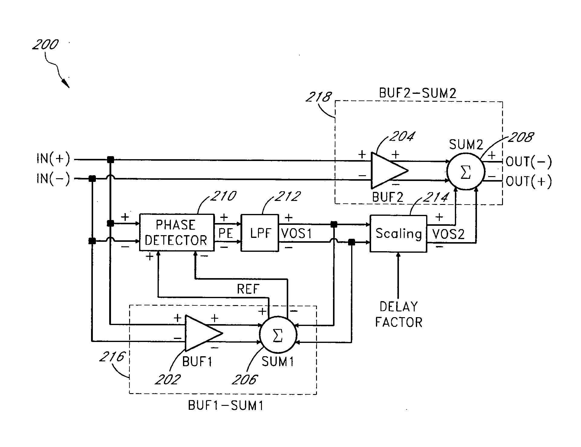
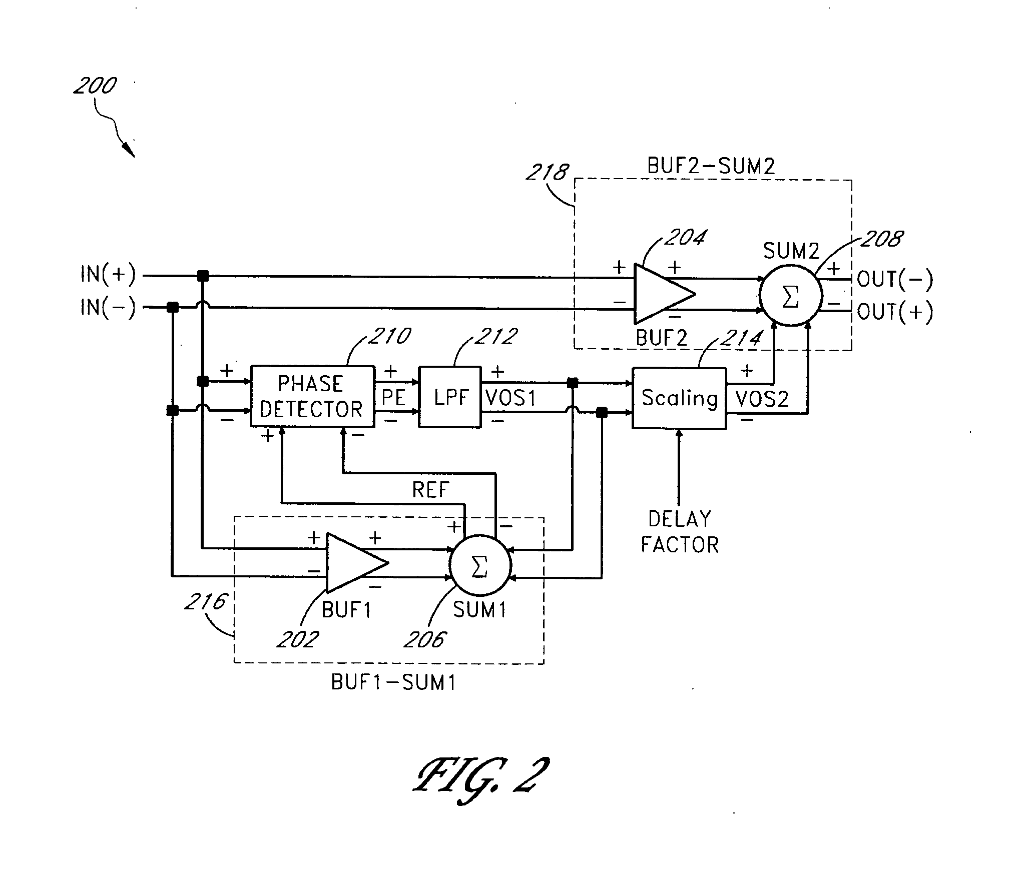
[0033] The present invention relates to a method and apparatus for controlling the phase delay of a clock with high resolution in the delay. While the specifications describes several example embodiments of the invention, it should be understood that the invention can be implemented in many way and is not limited to the particular examples described below or to the particular manner in which any features of such examples are implemented.

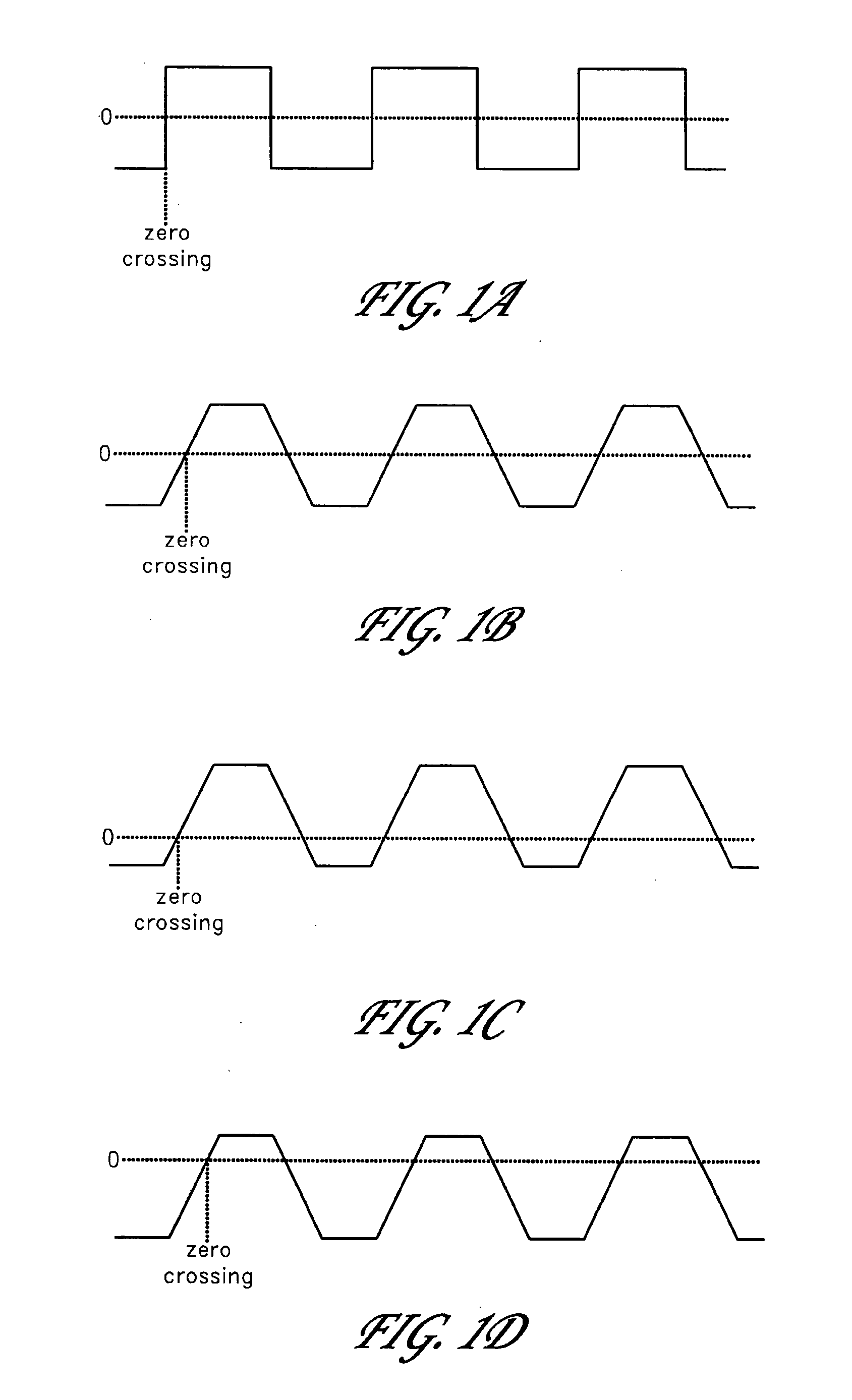
[0034] An ideal clock signal has an infinite slew rate, as shown in FIG. 1A. In practice, a realistic clock is slew-rate limited and therefore rises almost linearly near the zero crossing, as shown in FIG. 1B. Adding a positive DC offset to the slew-rate limited clock, pulls the zero-crossing point ahead and therefore the clock phase is advanced, as shown in FIG. 1C. Adding a negative DC offset to the slew-rate limited clock, pushes the zero-crossing point behind and therefore the clock phase is delayed, as shown in FIG. 1D. Once the slew-rate is kn...


PUM


Abstract

In an embodiment, a fine resolution of variable clock delay is implemented using a variable DC offset having fine resolution. The proportional ratio between the DC offset and the phase delay / advance of the clock is calibrated in a closed-loop manner. In an embodiment, in a calibration circuit, an adaptive positive DC offset is added to the output of a delay buffer to advance the phase of the clock output, which also has a phase delay from the delay buffer. The DC offset is adjusted in a closed-loop manner to make the phase advance, due to the DC offset, compensate for the phase delay, due to the delay buffer. Once the phase relationship of the DC offset to the clock phase advance is calibrated, the DC offset can be scaled and added to the output of another buffer of the same type to achieve a desired phase delay or advance of the clock signal.

Description

[0001] The present application claims priority benefits under 35 U.S.C. § 119(e) from U.S. Provisional Application No. 60 / 594,180, filed on Mar. 17, 2005, entitled “Variable Delay Clock Synthesizer,” which is hereby incorporated herein in its entirety by reference.BACKGROUND OF THE INVENTION [0002] 1. Field of the Invention [0003] The present invention relates to a method and apparatus for generating a variable delay clock and in particular to a system of controlling the delay of a clock with high resolution in the delay. [0004] 2. Description of the Related Art [0005] There are several methods to delay a clock signal. One method to delay a clock is to insert a delay buffer, such as a CMOS delay buffer, in the clock signal. A CMOS delay buffer typically comprises two CMOS inverters, each of which can comprise a NMOS transistor and a PMOS transistor. The delay to the clock caused by the buffer depends on many factors, including the clock speed, the transistor sizes, the supply voltag...

Claims


Application Information

Patent Timeline
IPC IPC(8): H03L7/06
CPCH03L7/0812H03L7/0896H03L7/0816
Inventor LIN, CHIA-LIANGCHOU, GERCHIH
Owner REALTEK SEMICON CORP
Learn More