Space / time / polarization adaptive antenna for ESM / ELINT receivers

a space/time/polarization and adaptive antenna technology, applied in direction finders using radio waves, polarisation/directional diversity, instruments, etc., can solve the problems of blocking the detection of desired signals that are near or within the bandwidth of the reject filter, wideband design, and completely inhibiting the detection of desired pulse signals. , to achieve the effect of suppressing high duty interference and high in-band interferen

Inactive Publication Date: 2006-09-21
SIERRA NEVADA CORP
View PDF8 Cites 25 Cited by
  • Summary
  • Abstract
  • Description
  • Claims
  • Application Information

AI Technical Summary

Benefits of technology

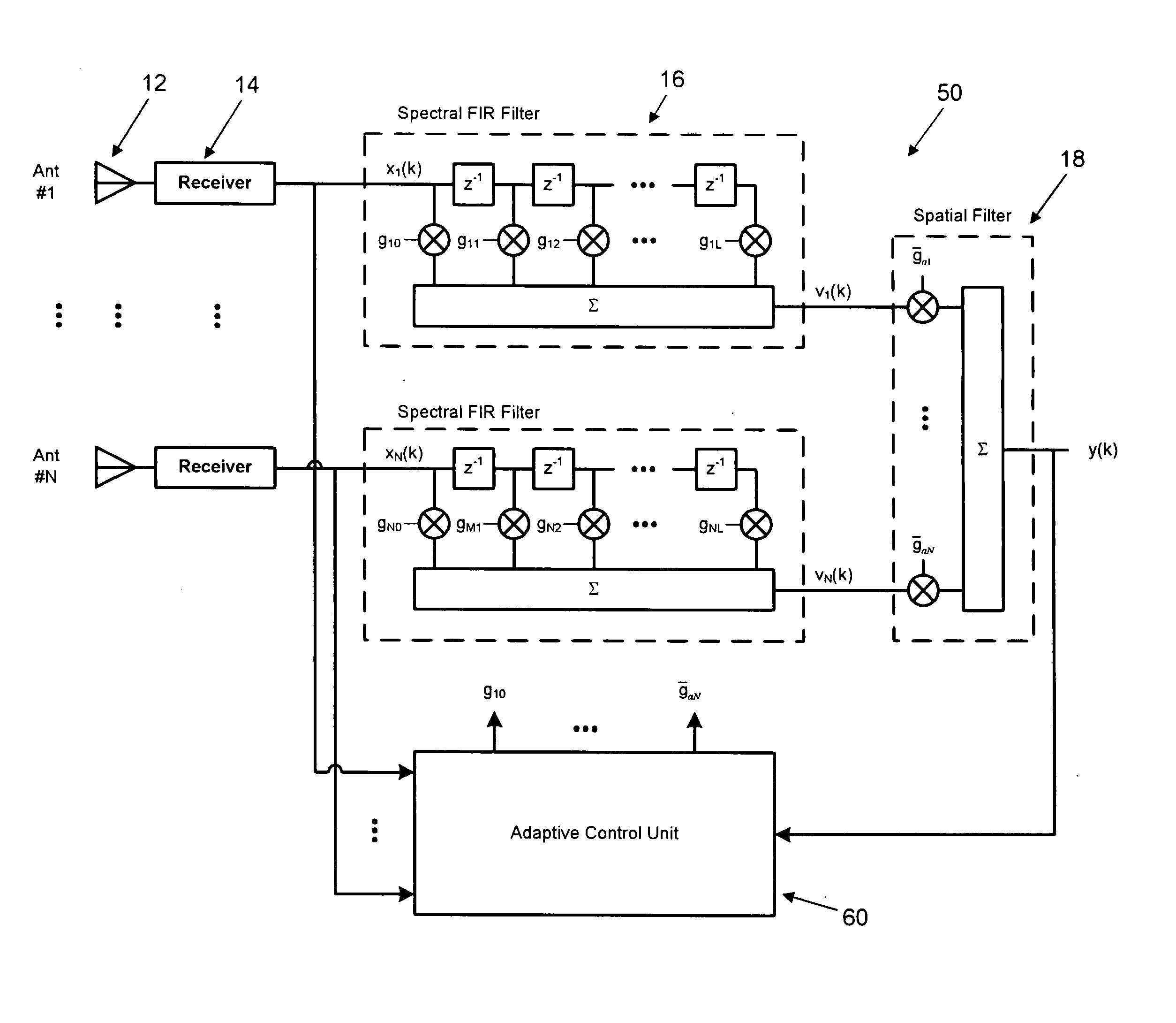
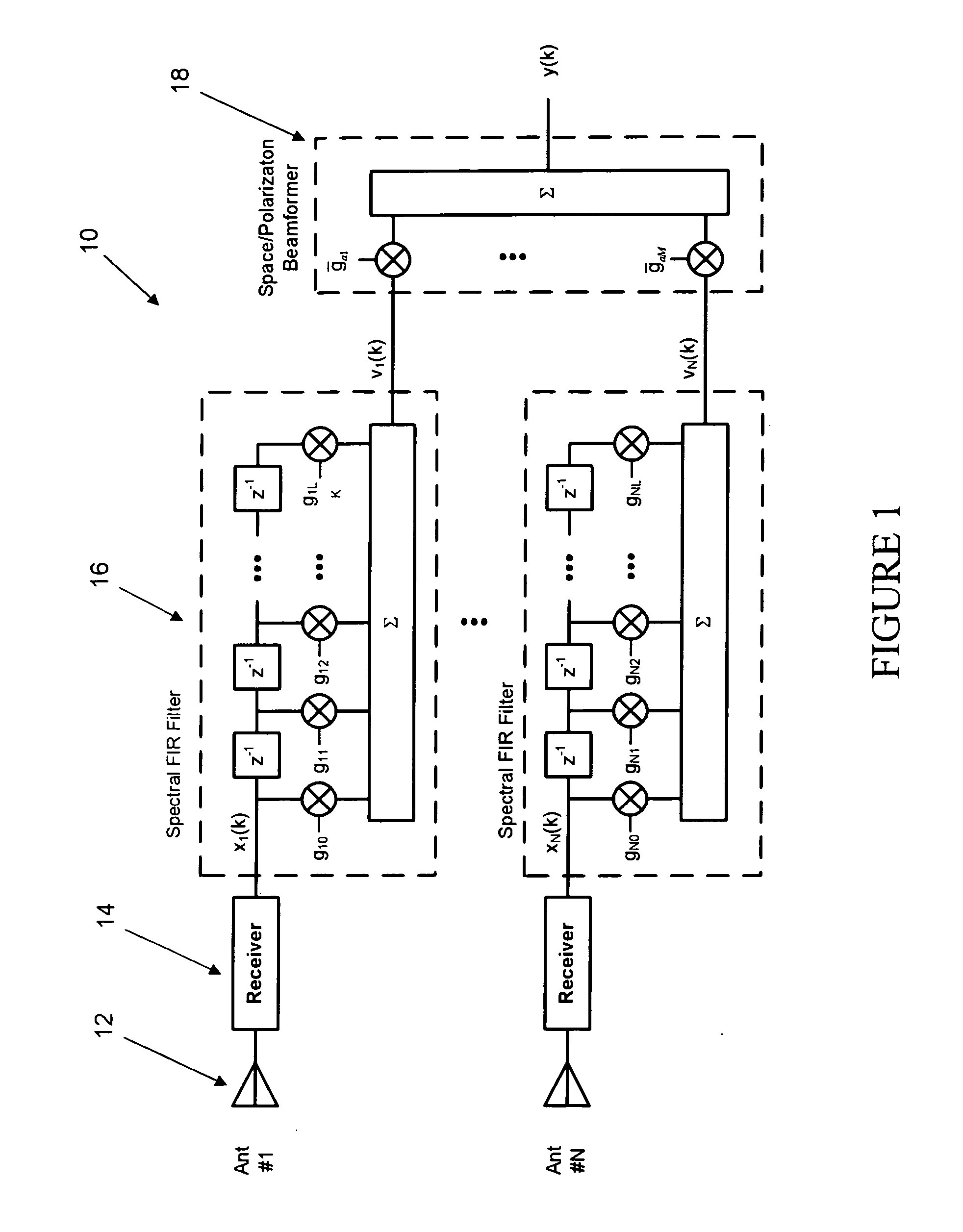
[0005] The adaptive interference canceller described in this invention is able to solve the above problems by employing three domains (spatial, spectral or time, and polarization) to suppress high duty interference while allowing the desired pulse signals to be detected and processed in the presence of high levels of in-band interference.

Problems solved by technology

However, wideband designs are susceptible to blockage from high level, high duty cycle or continuous waveform in-band interference (which is increasingly likely due to the wide bandwidth) that can completely inhibit the detection of the desired pulse signals.
Such interference can be due, for example, to nearby high power jammers and data links.
Tunable band reject filters have also been employed to remove high duty cycle interference but this can block detection of desired signals that are near or within the bandwidth of the reject filter.
Channelized receivers have been introduced to mitigate the limitations of narrow band tuners but these still remain susceptible of channel blockage from high duty cycle interference.

Method used


Image

  • Space / time / polarization adaptive antenna for ESM / ELINT receivers
  • Space / time / polarization adaptive antenna for ESM / ELINT receivers
  • Space / time / polarization adaptive antenna for ESM / ELINT receivers

Examples


case 1

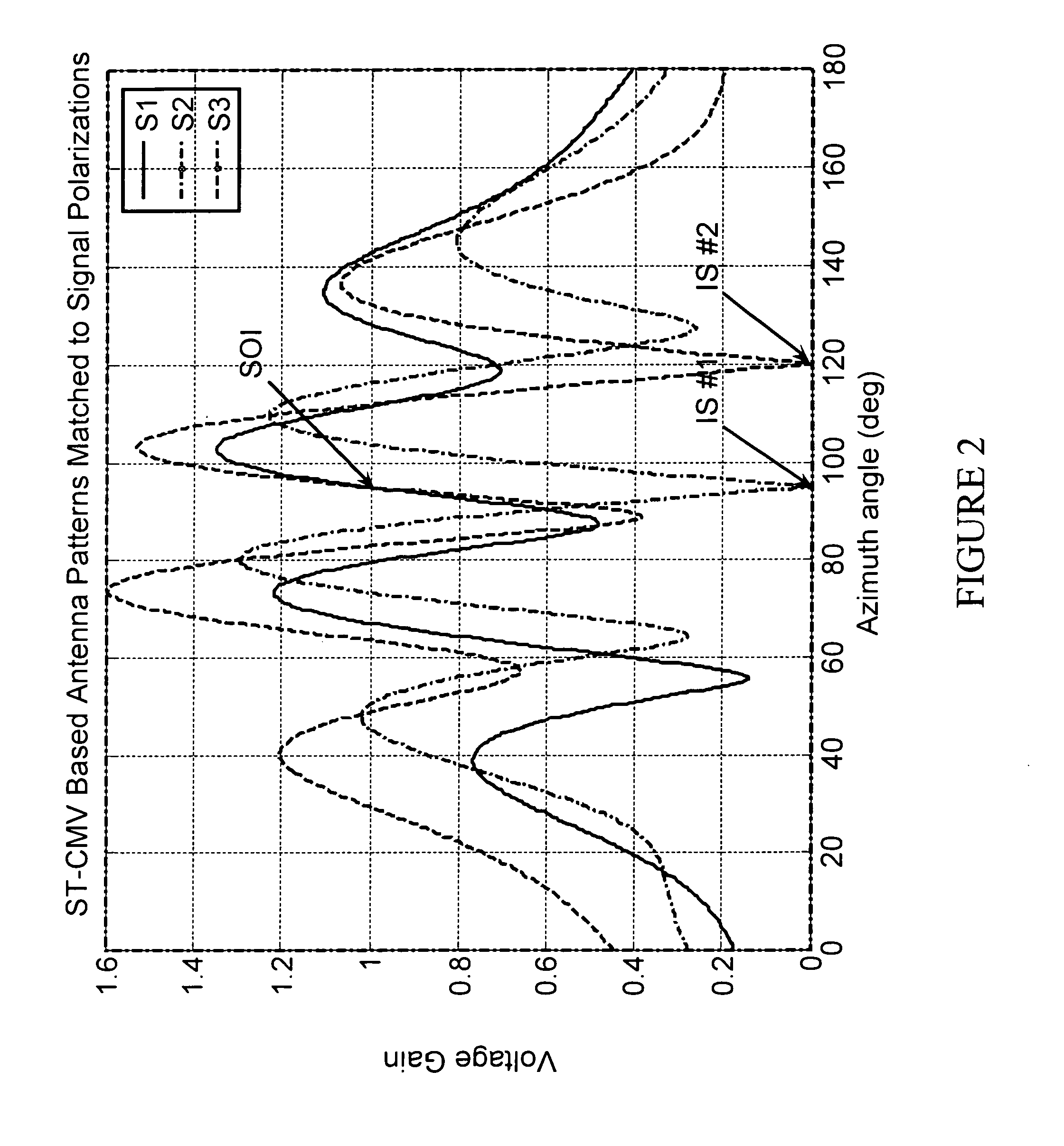
[0077] Case 1 involved only two signals, the SOI and one interfering signal at the same angle and frequency, but different polarizations. FIGS. 7 and 8 show the resulting antenna patterns for the SP-CMV and STP-CMV methods for the polarizations corresponding to the two signals. Note that both methods set the antenna gain to unity for the polarization and azimuth of the SOI as required by the constraint. Also, both methods produce nulls at the angle and polarization of the interfering signal. FIG. 9 shows the envelope of the beamformer output without adaptation and FIGS. 10 and 11 show the resulting signal envelope after adaptation for the two methods. Note that the STP-CMV method produces slightly better results.

case 2 adds

[0078] Case 2 adds interfering signal (#3 from Table 1) which is a wideband signal at a lower frequency (785 MHz), different azimuth angle (45 deg) and polarization (RHC). FIGS. 12 and 13 show the adapted pattern using the SP-CMV and STP-CMV methods for this signal set, and FIGS. 14 and 15 show the envelope of the adapted beamformer outputs. Note that while the SP-CMV produces a deeper null than the STP-CMV method at the azimuth of the added signal (i.e. 45 degrees), the envelope of the STP-CMV method shows much more suppression of the total interference. This demonstrates the improved capability that the FIR filters bring to the process.

case 3 adds

[0079] Case 3 adds another interfering signal (#4 from Table 1) to the signal environment. This signal is also a WBGN signal with a carrier frequency of 815 MHz, azimuth angle of 135 degrees and a slant left polarization. FIGS. 16 and 17 show the adapted antenna patterns for this signal set using the SP-CMV and STP-CMV methods, and FIGS. 18 and 19 show the resulting envelopes for the two techniques. Again, note the formation of a null at 135 degrees corresponding to the azimuth of the added signal. Also note that the envelope corresponding to the SP-CMV method is much degraded, indicating that it has reached its limit, while the envelope corresponding to the STP-CMV method still shows a signal-to-interference ratio (SIR) of nearly 30 dB.


PUM


Abstract

An adaptive array for detecting a signal of interest (SOI) that includes antenna elements, digital Finite Impulse Response (FIR) filters having programmable filter weights, a digital beamformer having programmable array weights and an adaptive control unit. Each antenna output signal is processed by an FIR filter to produce a filtered element signal. The filtered element signals are combined by the beamformer to produce an adaptive array output. The adaptive control unit adjusts the filter and array weights to maximize the adaptive array response to the SOI while minimizing the response to interfering signals. The adaptive control unit can use the frequency, look angle or polarization of the SOI, to constrain the spatial gain or polarization in the direction of the SOI, or to form a pass band at the SOI frequency. The adaptive control unit can equalize the beamformer frequency response to compensate for dispersion introduced by diverse antenna locations.

Description

[0001] This application claims the benefit of U.S. Provisional Patent Application Ser. No. 60 / 657,048, filed Feb. 28, 2005, titled CMV SPACE-TIME POLARIZATION ADAPTIVE ARRAY, the disclosure of which is expressly incorporated by reference herein.TECHNICAL FIELD OF THE INVENTION [0002] The present invention relates to methods and systems for signal detection. More specifically, the invention relates to methods and systems of using multiple antennas to form an adaptive array that can suppress in-band interfering signals while at the same time receiving one or more desired signals of interest. BACKGROUND OF THE INVENTION [0003] Electronic support measure and electronic intelligence (ESM / ELINT) receivers typically are designed with wide instantaneous RF bandwidths to intercept pulse signals from multiple emitters over broad frequency regions with high probability of intercept (POI). Since most signals tend to have narrow pulse widths and the average combined pulse rates are low, a high p...

Claims


Application Information

Patent Timeline
Patent Type & Authority Applications(United States)
IPC IPC(8): H01Q3/00G01S3/16
CPCH01Q3/2605H04B7/0845H04B7/10
Inventor KOLANEK, JAMES
Owner SIERRA NEVADA CORP
Why Eureka
Try Eureka