Cryogenic, ultra high-speed rolling bearing

a high-speed rolling bearing and cryogenic technology, applied in the direction of rolling contact bearings, shafts and bearings, rotary bearings, etc., can solve the problems of increasing manufacturing costs, complicated manufacturing processes, and inability to use bearings under cryogenic conditions, so as to improve adhesive strength and hence abrasion resistance, and reduce manufacturing costs to a large extent. , the effect of simple manufacturing processes

Inactive Publication Date: 2006-09-21
IHI CORP +2
View PDF7 Cites 13 Cited by
  • Summary
  • Abstract
  • Description
  • Claims
  • Application Information

AI Technical Summary

Benefits of technology

[0013] The present invention has been made to solve the above-described problems. In other words, it is an object of the present invention to provide, as an alternative to the conventional cryogenic, ultra high-speed rolling bearings, a cryogenic, ultra high-speed rolling bearing capable of: 1) maintaining a low friction coefficient and abrasion resistance required at cryogenic temperatures between about −260° C. and −160° C. without use of a fluid lubricant such as oil and grease; 2) being applied for such ultra-high rpm use that the DN value is about two millions or more and the rotational speed is about eighty thousands rpm or more; and 3) reducing manufacturing costs.

Problems solved by technology

However, oil or grease, typically used as a bearing lubricant, cannot be used for bearings used under such cryogenic conditions.
However, there are problems that this manufacturing method requires complicated manufacturing processes and increases manufacturing costs.

Method used


Image

  • Cryogenic, ultra high-speed rolling bearing
  • Cryogenic, ultra high-speed rolling bearing
  • Cryogenic, ultra high-speed rolling bearing

Examples


example 1

Comparative Test 1 on Coating Materials

[0063] In order to evaluate coating materials, a comparative test was done on PTFE with a small amount of anti-wear additive (TP1), PTFE with a medium amount of anti-wear additive (TP2), PTFE with a large amount of anti-wear additive (TP3), and TP3 with a low-temperature sliding additive (TP4) . The small, middle, and large amounts of anti-wear additive mean that the additive ratio of the same anti-wear additive increases in this order. The sliding additive different from the anti-wear additive was added to TP4 in an adequate amount.

[0064] The test was carried out on retainer materials TP1 to TP4 set as pins in a pin-on-disk type transfer tester at a cryogenic temperature (−196° C.) . In this test, the ratio of metal contact (%) was also determined from electric resistance between a ball and a rotating plate in the transfer tester. The test results are shown in FIGS. 3, 4, 5 and Table 1 (under cryogenic conditions).

TABLE 1Cryogenic Temperat...

example 2

Comparative Test 1 on Coating Materials

[0069] In order to further evaluate coating materials, four kinds of PTFE-based test materials (TP5 to TP8) with anti-wear additive and the like added thereto were prepared and the same test as on TP3 and TP4 was carried out at a cryogenic temperature (−196° C.). The test results are shown in FIGS. 6 and 7.

[0070]FIG. 6 is a line chart showing variations in pin friction coefficient at the cryogenic temperature. It is found from this chart that all of TP4 to TP7, except TP8, have low friction coefficients equivalent to conventionally proven products.

[0071]FIG. 7 is a bar chart for comparing the amounts of abrasive wear on the test materials at the cryogenic temperature. It is found from this chart that, though the amounts of abrasive wear on TP3, TP6, and TP8 are relatively large, those on TP5 and TP7 are better than conventionally proven products.

[0072] The above-mentioned results confirm that TP5 and TP7 has performance equivalent to conven...

example 3

Performance TEST on Bearing

[0073] The bearing of the present invention was actually rotated at ultra-high speeds under cryogenic conditions to test its performance.

[0074]FIG. 8 is a sectional view of the structure of a performance tester to test the performance of the cryogenic, ultra high-speed rolling bearing according to the present invention. In this tester, two sets of sample bearings 34 are incorporated with a radial turbine 36 provided at an end of an ultra high-speed rotating shaft 35. The radial turbine 36 was driven by gasified liquid hydrogen (at about −253° C.) and the bearing was cooled by liquid hydrogen.

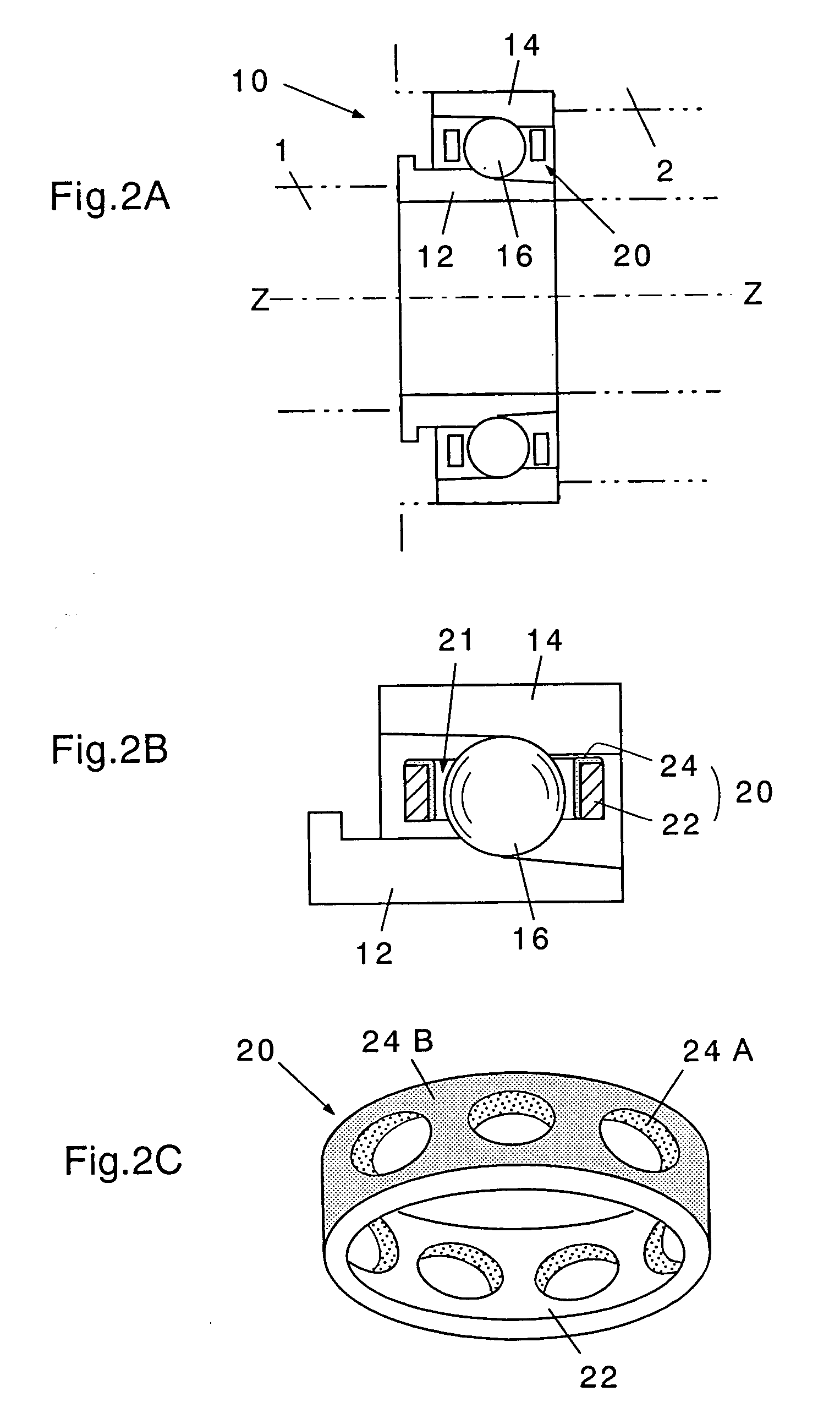
[0075] The bearing 34 of the present invention was made up by making the retainer body 22 of A5056 aluminum alloy, forming a coating film corresponding to TP2 in Example 1 on the inner surfaces of the pocket holes 21 and the outer circumference of the guideway, baking the coating film, and polishing the outer circumference of the guideway to predetermined dimensions...


PUM


Abstract

A cryogenic, ultra high-speed rolling bearing comprises an inner ring 12 fitted onto a rotating shaft rotating at ultra-high speeds under cryogenic conditions, an outer ring 14 concentrically surrounding the inner ring with a space therebetween and fitted onto a fixed portion, a plurality of rolling elements 16 rotatably inserted in the space between the inner ring and the outer ring, and a retainer 20 located between the inner ring and the outer ring to hold the rolling elements at intervals therebetween. The retainer 20 comprises a retainer body 22 having a plurality of pocket holes 21 formed therethrough in a radial direction to contain the rolling elements at intervals therebetween, and a solid lubricant film 24 (pocket hole coating 24A and guideway coating 24B) provided on the inner surfaces of the plurality of pocket holes and a guideway contacting the inner or outer ring and having transfer properties and a low friction coefficient enough for cryogenic conditions.

Description

BACKGROUND OF THE INVENTION [0001] 1. Field of the Invention [0002] The present invention relates to a cryogenic, ultra high-speed rolling bearing used in a cryogenic liquefied gas such as liquid hydrogen, liquid oxygen, or liquefied natural gas. [0003] 2. Description of the Related Art [0004] The boiling point of liquid hydrogen, liquid oxygen, or liquefied natural gas (methane) at 1 atmospheric pressure is about −253° C., −183° C., or −162° C., respectively. A bearing used in such a liquefied gas is employed for high speed rotating machinery (for example, turbopump) used in a rocket engine or the like. [0005] The high speed rotating machinery for such a cryogenic liquefied gas requires a very high DN value (bearing bore by rotational speed) as one of the operating conditions of the bearing (for example, two millions or more), so that the retainer used for the rolling bearing needs to be small and lightweight with high strength. [0006] However, oil or grease, typically used as a be...

Claims


Application Information

Patent Timeline
Patent Type & Authority Applications(United States)
IPC IPC(8): F16C33/44
CPCF16C19/163F16C33/44F16C33/445F16C33/6696Y02T10/86
Inventor OTA, TOYOHIKOMIHARA, REIOKAYASU, AKIRANAKAMURA, SHOHEICHEN, SICHAO
Owner IHI CORP
Why Eureka
Try Eureka