Structure for preventing shaft of constant velocity joint from coming off

a constant velocity joint and structure technology, applied in the direction of manufacturing tools, furniture parts, couplings, etc., can solve the problems of not showing how to manage the angle of the sidewall of the groove, requiring a lot of time and expense to machine the tool, etc., to reduce the man-hours required for parts control, and preventing the effect of retaining rings

Inactive Publication Date: 2006-09-21
NTN CORP
View PDF7 Cites 13 Cited by
  • Summary
  • Abstract
  • Description
  • Claims
  • Application Information

AI Technical Summary

Benefits of technology

[0014] Accordingly, it is possible to produce specification with which disassembly is possible by a structure of a side wall of a retaining ring groove formed on a shaft without constituting an inner joint member and a retaining ring each as exclusive member, and specification with which disassembly is not possible, and therefore, shared use of parts is made possible thereby reducing man-hours required for parts control.
[0015] In order to obtain specification which allows disassembly of an inner joint member and a shaft, with specification free from at least two contacting faces on a side wall of a retaining ring groove of a shaft, and step part, by which such a force is given to move the retaining ring in a radial contracting direction using slope part at inner joint member side as slope surface, when a force is applied to the shaft in a pulling out direction, diameter of the retaining ring is contracted, the retaining ring is moved in the insertion hole, and prevention by the retaining ring can be prevented.

Problems solved by technology

However, this mechanism requires much time and expenses to machine the tool engagement groove on the inner joint member.
The publication, however, does not show how to manage an angle of a groove sidewall for effecting two types of configurations where the one allows a shaft to be pulled out and the other does not.

Method used


Image

  • Structure for preventing shaft of constant velocity joint from coming off
  • Structure for preventing shaft of constant velocity joint from coming off
  • Structure for preventing shaft of constant velocity joint from coming off

Examples


Embodiment Construction

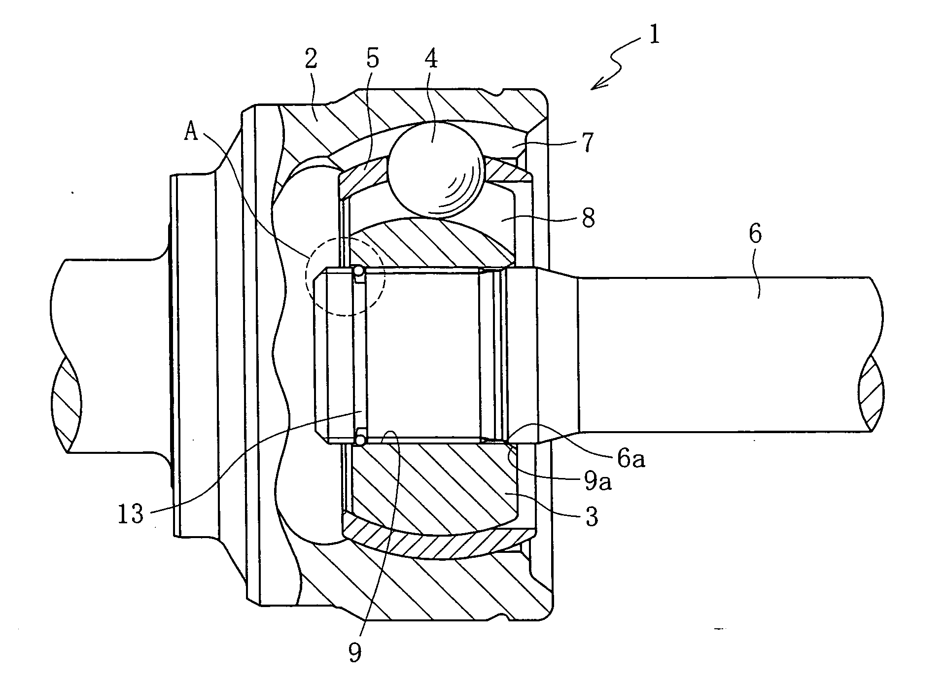
[0024] Referring now to FIG. 1 to FIG. 8, embodiments of the present invention will be explained hereafter. For convenience of explanation, front edge side denotes left side on the drawing and anti-front edge side denotes right side on the drawing. For convenience, explanations will be given referring to a fixed type constant velocity joint as shown in FIG. 1 in which the inner joint member is also referred to also as an inner ring.

[0025] As shown in FIG. 1, fixed type constant velocity joint 1 comprises outer ring 2, inner joint member 3, torque transmission ball 4, and cage 5 for torque transmission ball 4. Further, shaft 6 for transmitting torque is mounted to the inner joint member 3 in an engaging manner. The constant velocity joint, not limited to the fixed type constant velocity joint 1, may be sliding movement type constant velocity joint such as double-offset type, cross-globe type, tripod type or the like. Meanwhile, inner joint member in the double-offset type and cross-...


PUM


Abstract

The present invention presents a structure for preventing a shaft of constant velocity joint from coming off which allows changing design of connection between the shaft and an inner joint member to a type for disassembly or anti-disassembly. The anti-disassembly type is realized in such a manner that a wall at an opposite side to a shaft pulling out direction of a retaining ring groove of the shaft is used as a contacting part to a retaining ring, wherein at least two points are formed on the contacting part, one of which is on a perpendicular surface and the other is a corner of the contacting part, these two points are contacted with an inner surface of the retaining ring thereby provides the anti-disassembly type for preventing the ring from being contracted in a radial direction.

Description

FIELD OF THE INVENTION [0001] The present invention relates to a spline engagement structure for coupling an inner joint member with a shaft of constant velocity joints used in automobiles and various industrial equipments,. BACKGROUND OF THE INVENTION [0002] In conventional constant velocity joints for driving system or the like of automobiles, an inner joint member and a shaft are engaged detachably while employing a structure for preventing the shaft from coming off for reduction of maintenance man-hours of replacement of boots or the like. With this structure, a groove is formed at end face of the shaft, a retaining ring is provided to this groove, and the shaft is engaged with a contacting face being formed on the inner joint member by means of elastic expansion of the retaining ring. A mechanism used here is such that a corner is provided to a contacting face that interferes with the retaining ring when the shaft is pulled out, and disengagement is performed by radially contra...

Claims


Application Information

Patent Timeline
Patent Type & Authority Applications(United States)
IPC IPC(8): F16C3/00
CPCF16D3/223F16D2003/22313Y10T403/7033Y10S464/906Y10S403/07F16D2300/12F16D2001/103F16D1/116
Inventor FUKUMURA, YOSHIKAZUUENO, TSUYOSHISHINBA, CHIKAYASHIBATA, TAKAAKI
Owner NTN CORP
Why Eureka
Try Eureka