Safety syringe

a safety syringe and syringe technology, applied in the field of safety syringes, can solve the problems of high manufacturing cost, inability to widely adopt most syringes, and considerable latent safety problems, and achieve the effect of convenient operation, low manufacturing cost and reliable auto-locking function

Inactive Publication Date: 2006-09-21
WANG XIPING
View PDF4 Cites 22 Cited by
  • Summary
  • Abstract
  • Description
  • Claims
  • Application Information

AI Technical Summary

Benefits of technology

[0026] Also, the present invention has a reliable function of auto-locking; therefore, once the syringe is used, the plunger has been locked in the syringe barrel and cannot be pulled out any longer, any attempt to use the syringe again will cause the plunger broken and the syringe damaged, thus ensuring a one-time use.
[0027] The piston of the present invention can be assembled optimally. Not only the structure of the invention is simplified to make operation convenient (the invention is fully equal to common syringes with respect to injection operation), the invention is but also designed to meet the requirements to control the accuracy of used dosage for injection, to guarantee the operational safety of blood withdrawal, and to make the variation of pushing force of injection negligible so that the easiness of injection is not affected essentially. Furthermore, initiating the safety mechanism (to make sliding casing moved forward) will not be started until injection is finished, therefore it does not affect the patients negatively.
[0028] The present invention has a simplified structure considering the medical fluid in the syringe. The parts of syringe that contact with the medical fluid are only the syringe barrel and the piston (fully equal to common syringes), thereby reliably avoiding the medical fluid to be contaminated and guaranteeing the safety of injection.
[0029] The present invention makes a change of standard needle easy so that it satisfies the different requirements of use.
[0030] The structures of the parts of the present invention is relatively concise among the like safety syringes, so it is convenient for manufacturing and easy for assembling, thus leading to a high cost effectiveness.
[0031] The present invention can make the automatic or semi-automatic assembly easily realized, thereby creating a better condition for mass production.

Problems solved by technology

However, commonly used disposable syringes may occasionally prick medical staffs after injection or hurt the workers processing medical waste later, thereby existing considerable latent safety problems.
Although there have been many domestic or international patents in relation to disposable safety syringes, most of the syringes may not be widely adopted due to complicated configuration, high cost for manufacturing, inconvenience for use and functional inadequacy.
First, the overall configuration of the invention is complicated; thereby making its dies possess complex structures that shorten the service life of the dies.
As a result, the investment on manufacture and cost goes up.
The second, the invention comprises many parts, which raise the difficulty of assembly process as well as production cost.
Yet no auto-latching and auto-disable functions regarding to the whole syringe are implemented.
Therefore, some other parts (e.g. plunger) that might be taken off to reuse are still latent safety problems to patients.
The fourth, the invention reserves a defined space at the front end of the syringe, thereby bringing a considerable inconvenience for some applications of the syringe, e.g. blood withdrawal.

Method used


Image

  • Safety syringe
  • Safety syringe
  • Safety syringe

Examples


Embodiment Construction

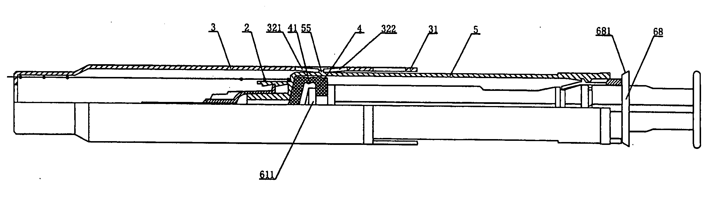
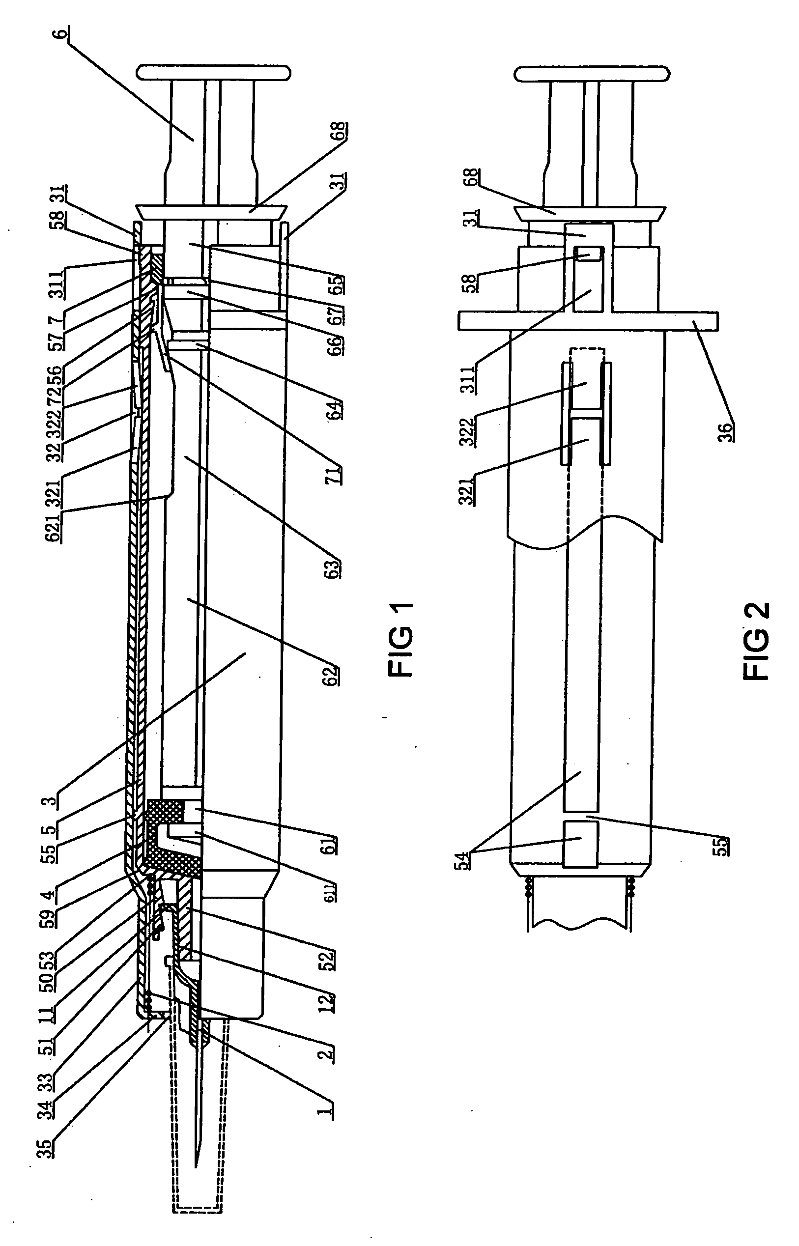
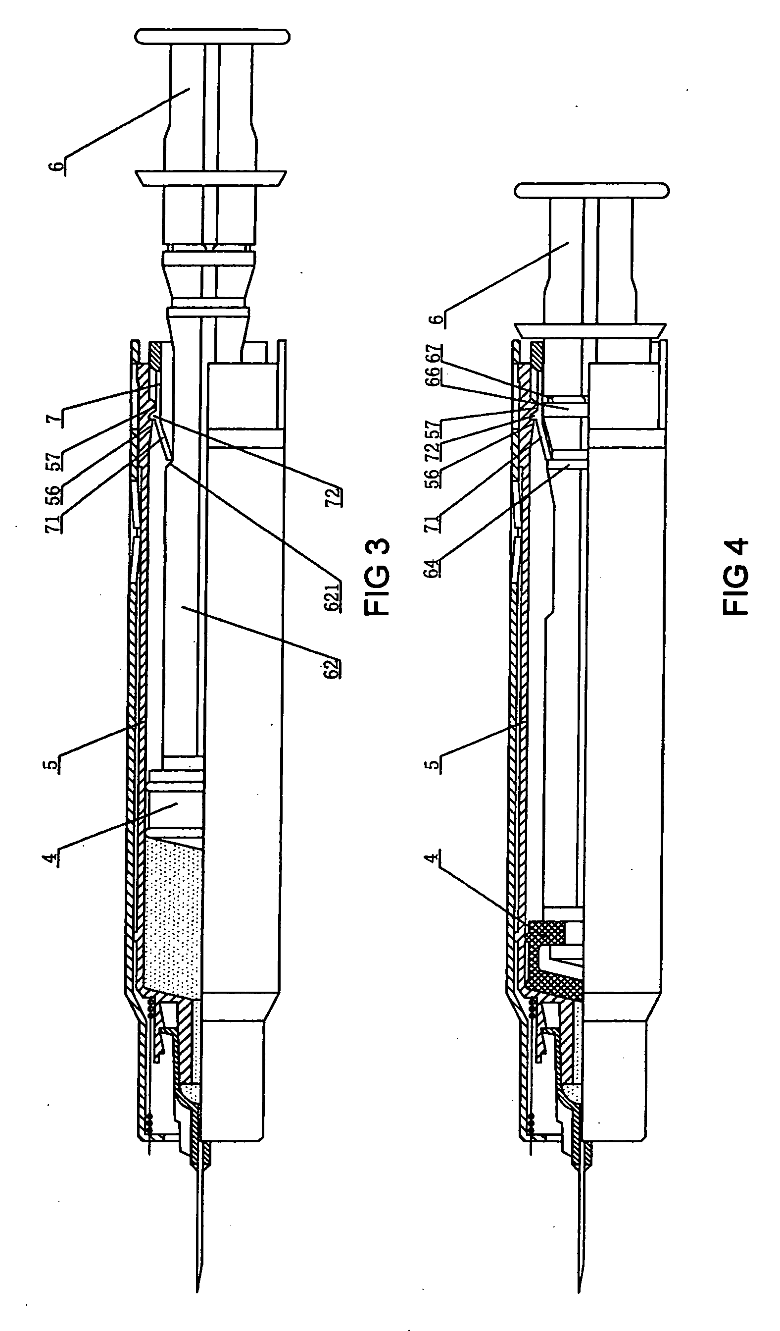
[0045]FIG. 1 and FIG. 2 show a schematic view of the configuration of an embodiment according to the present invention, namely a safety syringe in an unused state after its assembly. The syringe comprises a needle 1, a spring 2, a sliding casing 3, a piston 4, a syringe barrel 5, a plunger 6 and a latching casing 7.

[0046] The injection needle 1 may be engaged with a needle luer skirt 51 at the front end of the syringe barrel 5 by screwing the flange 11 on the needle base so that the inner hole 12 of the needle base engages with a luer tip 52 of the syringe barrel.

[0047] The sliding casing 3 is moveably sleeved on the outside of the syringe barrel 5. The rear portion of the sliding casing 3 is provided with two elastic extension plates 31, on each of which a connection part is respectively provided. In this embodiment, the connection part is a locking notch 311 respectively grooved on each of the extension plates 31. The middle portion of the sliding casing has two short grooves 32...


PUM


Abstract

The present invention discloses a safety syringe and aims to provide simple structure, convenient use, and low cost, and to make the syringe have needle protection functionality and become auto-disable. The present invention includes a sliding casing, a needle, a syringe barrel, a piston, a latching casing, a spring and a plunger inside the syringe barrel, the present invention can be easily used to carry out an injection and to initiate its safety mechanism by a single hand. The sliding casing can be automatically positioned and locked in two directions; This design guarantees during processing the syringe after it is used, the pinhead is always protected by the sliding casing; The present invention also has a reliable function of auto-locking; Therefore, once the syringe is used, the plunger has been locked in the syringe barrel and can not be pulled out any longer; Any attempt to use the syringe again will cause the plunger broken and the syringe damaged, thus ensuring a one-time use.

Description

BACKGROUND OF THE INVENTION [0001] 1. Technical field [0002] The present invention relates to a safety syringe, particularly to an auto-disable safety syringe of needle-protective functionality. [0003] 2. Background of the Art [0004] At present, more and more diseases are contaminated through blood, bodily fluid, etc. One of main channels that cause disease to spread is using the same syringe for multiple times and inappropriately handling the needle of a syringe after it is used. However, commonly used disposable syringes may occasionally prick medical staffs after injection or hurt the workers processing medical waste later, thereby existing considerable latent safety problems. [0005] Although there have been many domestic or international patents in relation to disposable safety syringes, most of the syringes may not be widely adopted due to complicated configuration, high cost for manufacturing, inconvenience for use and functional inadequacy. [0006] The patent of invention of f...

Claims


Application Information

Patent Timeline
Patent Type & Authority Applications(United States)
IPC IPC(8): A61M5/00A61M5/178A61M5/32A61M5/50
CPCA61M5/326A61M5/3271A61M2005/3247A61M2005/3261A61M2005/3264A61M2005/5073
Inventor WANG, XIPING
Owner WANG XIPING
Why Eureka
Try Eureka