Energy returning prosthetic foot

a prosthetic foot and energy-returning technology, applied in the field of prosthetic feet, can solve the problems of complex designs, frequent need for prosthetic limbs, and limitations, and achieve the effects of increasing the adjustability of the prosthetic foot, avoiding undesired noise, and reducing the cost of prosthetic limbs

Inactive Publication Date: 2006-09-21
AMERICAN PROSTHETIC COMPONENTS
View PDF6 Cites 57 Cited by
  • Summary
  • Abstract
  • Description
  • Claims
  • Application Information

AI Technical Summary

Benefits of technology

[0018] A further advantage of the present invention is that there are no moving or rotatably connected parts that may fail over time. Further, since none of the components of the present invention are movingly or rotatably connected to each other, and since none of these components rub against each other during use, the foot is free from undesired noises. There is therefore no need for noise abatement features.
[0019] A still further advantage of the present invention is that it is customizable to suit the specific needs of any given person. This is initially accomplished by selecting the appropriate blank foot from a given number of sizes of blank feet. The prosthetic foot can then be reduced from the initial size down to the desired length. Further, a left or right foot can be constructed as desired from a single blank. Still further, toes or toe like projections can be formed as desired to further add to the flexibility of the foot.
[0020] A still further advantage yet of the prosthetic foot of the present invention is that the present invention provides support to the person at mid-stance. This is accomplished by flexing of the heel strike due to contact with the ground, flexing of the toe plate due to contact with the ground, flexing of the adapter plate due to the weight of the person and compression of the momentum interrupter. These flexing and compressing components relieve problems that may normally be associated with flat foot, and the energy returned from the heel-strike assists the person in moving from mid-stance to toe-off.
[0021] A still further advantage yet of the prosthetic foot of the present invention is that stiffeners can be incorporated into the foot to further increase the adjustability of the prosthetic foot. The stiffeners can be mechanically adjustable stiffeners to provide even further adjustability to the present invention. The stiffeners can be placed between the adapter plate and the heel strike to provide additional support at heel-strike. A stiffener can also be incorporated into the foot to selectively reduce the compressibility of the momentum interrupter. Such stiffeners can be used as desired, such as when the person will be engaging in high impact environments such as playing sports, or when the person is a heavier individual.

Problems solved by technology

People frequently are in need of prosthetic limbs as a result of accidents, disease or birth defects.
Other designs are complex, and seek to simulate or copy the structure of the human foot.
While this foot may work well for its intended purpose, it is not without some limitations.
Another limitation of this foot is that there is no way to adjust the amount of flex of the uninterrupted component in order to accommodate for persons having various weights and / or lifestyles.
However, there are drawbacks also associated therewith.
One limitation is the lack of adjustability.
A further limitation is that the amount of energy return at toe-off consists of the energy stored during the flexing of the single uninterrupted component spanning from the ankle to the toe.
This foot, being an assembly, is relatively complicated when compared to the previously described prosthetic feet.
A further limitation of this foot is that there may be inherent noise problems incorporated into the design of the compressible elements.
One limitation with this foot is that the amount of energy return at toe-off consists of the energy stored during the flexing of the single uninterrupted component spanning from the ankle to the toe.
Another limitation of this foot is that there is no way to adjust the flexing settings of the single uninterrupted component to accommodate for persons having various weights and / or lifestyles.
A limitation of this foot is that it is lacking is adjustability.

Method used


Image

  • Energy returning prosthetic foot
  • Energy returning prosthetic foot
  • Energy returning prosthetic foot

Examples


Embodiment Construction

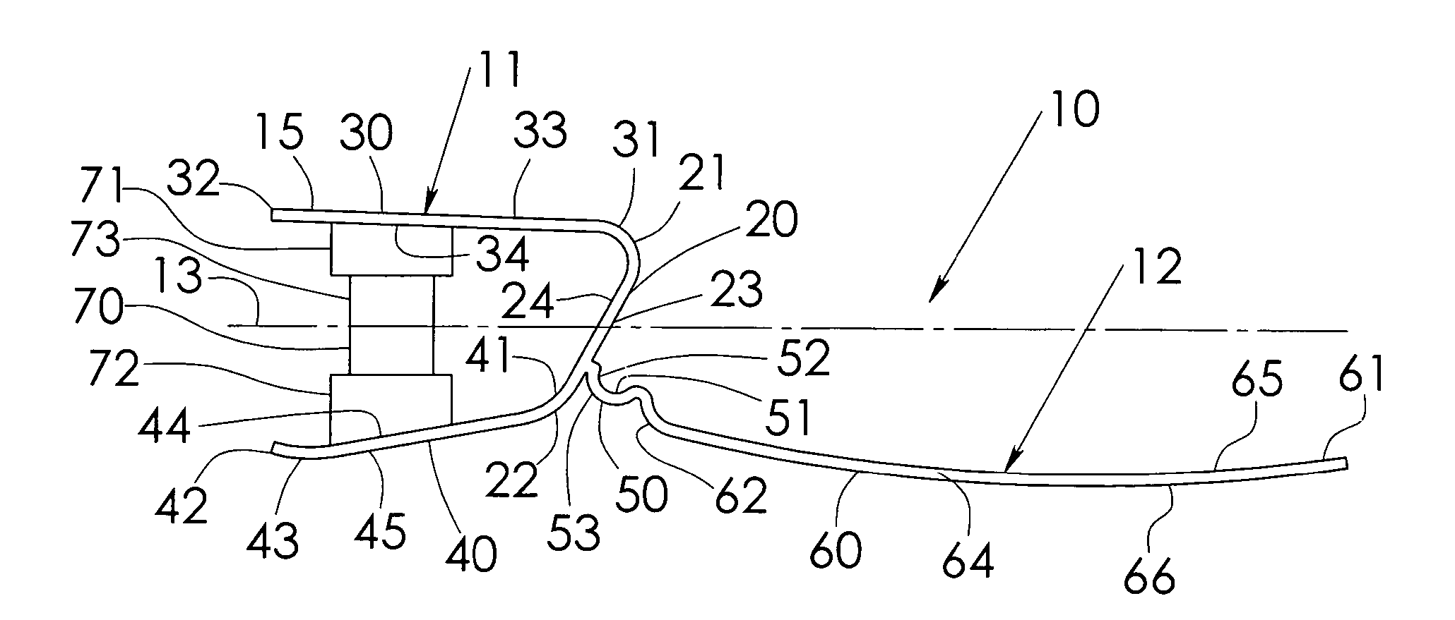
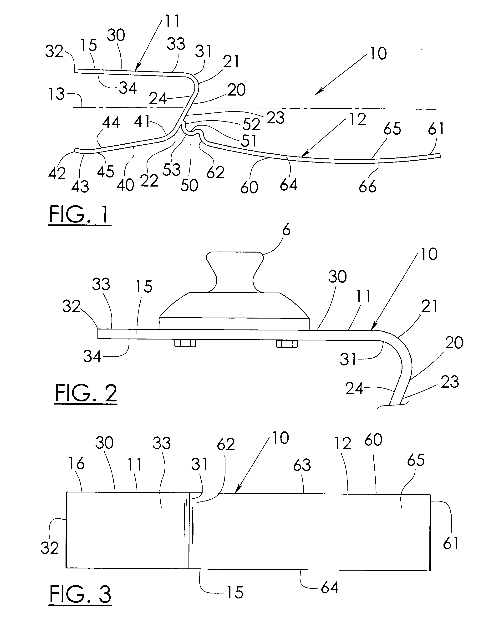
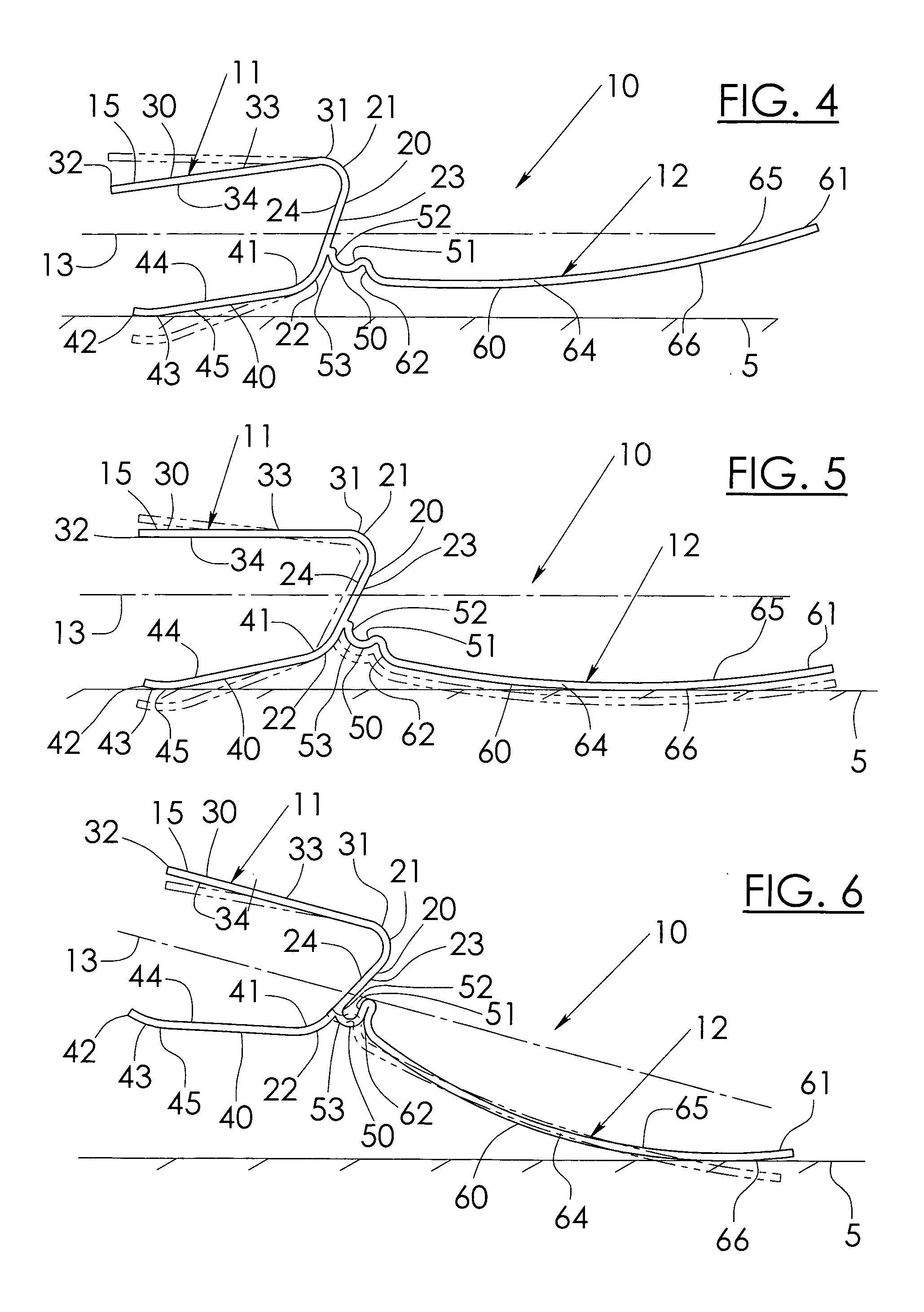
[0043] While the invention will be described in connection with several preferred embodiments, it will be understood that it is not intended to limit the invention to those embodiments. On the contrary, it is intended to cover all alternatives, modifications and equivalents as may be included within the spirit and scope of the invention as defined by the appended claims.

[0044] The prosthetic foot 10 of the present invention is preferably made from a carbon epoxy composite material. It will be understood that the present invention is not limited to being constructed of carbon epoxy composite material, and that other resilient materials can be used without departing from the broad aspects of the present invention.

[0045] The foot 10 is preferably made in blanks that can be reduced in size to form left and right feet, as desired, and shortened to meet the requirements of a particular person. Several size blanks can be made so that practitioners can select an appropriate blank for a st...


PUM


Abstract

The present invention relates to a prosthetic foot comprising a rear foot portion having an attachment platform and a heel strike, and a front foot portion having a momentum interrupter and a toe plate. As the foot approaches toe-off, the toe plate flexibly deflects upwards and the momentum interrupter compresses. The amount of returned energy at toe-off is comprised from stored flexural energy of the toe plate and stored expansive energy of the momentum interrupter. The toe plate of the present invention can have a split toe design. Further, mechanically adjustable stiffeners can be incorporated into the design if desired.

Description

BACKGROUND OF THE INVENTION [0001] 1. Field of the Invention [0002] The present invention relates to a prosthetic foot, and more particularly to an energy returning prosthetic foot comprising a momentum interrupter, that is flexible about many axis, and that is efficient at storing and returning energy during use. [0003] 2. Description of the Related Art [0004] People frequently are in need of prosthetic limbs as a result of accidents, disease or birth defects. The need for quality prosthetic feet is high. There have been many attempts to make suitable prosthetic feet, each desiring to reach goals of safety, functionality and comfort, among other qualities. The existing prosthetic feet have achieved varying levels of success at attaining each of these stated goals. Further, many strategies have been utilized in designing prosthetic feet. Some designs are relatively noncomplicated, and seek use a simple design. Other designs are complex, and seek to simulate or copy the structure of ...

Claims


Application Information

Patent Timeline
Patent Type & Authority Applications(United States)
IPC IPC(8): A61F2/66
CPCA61F2/66A61F2002/5038A61F2002/5043A61F2002/6614A61F2002/6621A61F2002/6642A61F2002/6671A61F2002/6685
Inventor CURTIS, MICHAEL J.
Owner AMERICAN PROSTHETIC COMPONENTS
Why Eureka
Try Eureka