Machine tool comprising parallel tool spindles that can be repositioned in relation to one another

a technology of parallel spindles and machine tools, applied in the field of machine tools, can solve the problems of inability to ensure the required accuracy during machining any longer in a process-reliable manner, and the accuracy of workpiece machining is not guaranteed, and achieves the effect of high clamping force, sensitive repositioning movement, and safe position

Active Publication Date: 2006-09-28
FFG WERKE +1
View PDF8 Cites 4 Cited by
  • Summary
  • Abstract
  • Description
  • Claims
  • Application Information

AI Technical Summary

Benefits of technology

[0011] As provided for under the present invention, the two spindles disposed horizontally or vertically in parallel axis to each other can be adjusted independently of each other in x and/or y direction in a simple manner by turning the eccentric bushes, in which they are eccentrically supported, around a definable angle. To this effect, the anti-twist securing and/or clamping means of the eccentric bushes within the stationary bracket is released at first so that the eccentric bushes can be turned and/or so that one of the eccentric bushes can be displaced in axial direction. During machining they are firmly arrested and/or clamped in the bracket. The clamping of the spindle units during machining is accomplished by using a clamping ring in the same manner as for example a belt pulley is fastened on a shaft. Thus it is possible to generate high clamping forces within a very restricted built space and the spindle is kept safely in its position even during severe machining.
[0012] The repositioning devices can be approached and activated particularly independent of each other. To adjust the eccentric bushes in x and y direction, the repositioning devices attack the eccentric bushes tangentially outside, with it being possible to drive them mechanically, electrically, or hydraulically. For transformation of the linear drive m

Problems solved by technology

These alterations partly might substantially affect the accuracy in workpiece machining, thus making it impossible to warrant the required accuracy during machining any longer in a process-reliable manner.
A compensation for position with regard to the distance in the plan

Method used


Image

  • Machine tool comprising parallel tool spindles that can be repositioned in relation to one another
  • Machine tool comprising parallel tool spindles that can be repositioned in relation to one another
  • Machine tool comprising parallel tool spindles that can be repositioned in relation to one another

Examples


Embodiment Construction

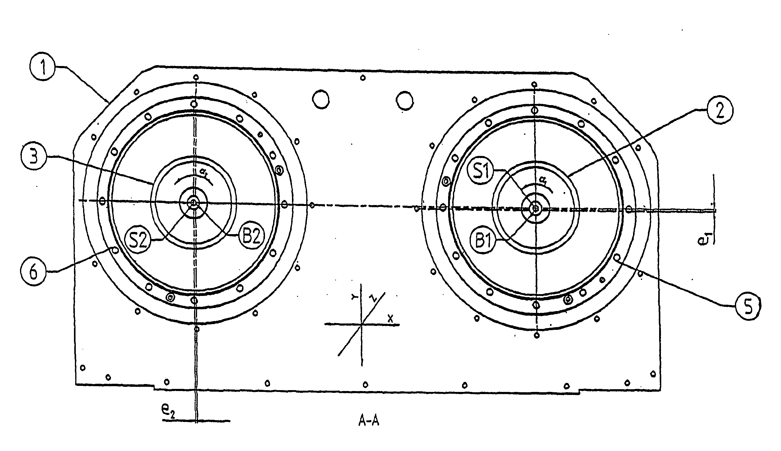
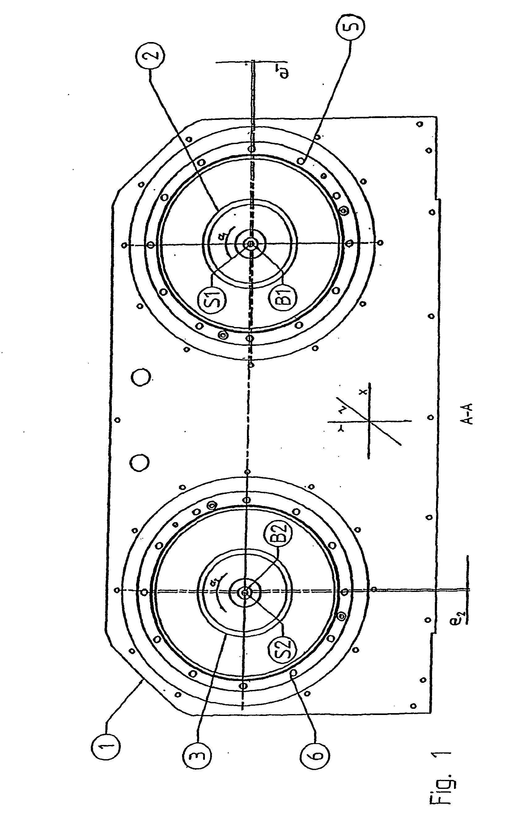
[0020] Referring to the drawings in particular, as schematically shown on FIG. 1, the two spindle units 2 and 3 which are disposed side by side in parallel to each other are firmly arranged eccentrically in an eccentric bush 5, 6 each. The eccentric bushes 5, 6 are mounted in bracket 1 of the machine tool in a bearing pivoting by angles α1 and α2 around central shafts B1 and B2. The central shaft S1 of spindle unit 2, when being in its base position in y-direction, has the eccentricity e1 versus the central shaft B1 of eccentric bush 5, while the central shaft S2 of spindle unit 3 in x-direction has the eccentricity e2 versus the central shaft B2 of eccentric bush 6. By twisting, e.g. eccentric bush 5, within the bracket 1 by an angle α1 around central shaft B1 just by a few angle degrees, the spindle unit 2 is repositioned particularly in x-direction. In the same manner, by twisting the eccentric bush 6, the spindle unit 3 firmly arranged therein is repositioned in y-direction. Whi...


PUM

PropertyMeasurementUnit
Lengthaaaaaaaaaa
Lengthaaaaaaaaaa
Lengthaaaaaaaaaa

Abstract

A machine tool is provided, in particular for the synchronous machining of workpieces. The tool includes two or more spindle units (2, 3), which run parallel in a machining unit and are designed to hold workpieces and repositioning devices for the precise adjustment of the position of the spindle units (2, 3) in relation to one another, preferably in all three directions x, y and z of the orthogonal co-ordinate system in the machining unit (4). The repositioning devices for displacing at least one of the spindle units (2, 3), at least in an x and/or y direction, include an eccentric bush (5, 6), which can be rotated about a central shaft (B1, B2) and locked and in which the spindle units (2, 3) are mounted eccentrically, parallel to the central shaft (B1, B2).

Description

CROSS REFERENCE TO RELATED APPLICATIONS [0001] This application is a United States National Phase application of International Application PCT / EP2004 / 001339 Feb. 13, 2004 and claims the benefit of priority under 35 U.S.C. § 119 of German Application DE 103 29 402.3 filed Jun. 28, 2003, the entire contents of which are incorporated herein by reference.FIELD OF THE INVENTION [0002] The invention relates to a machine tool, in particular for the synchronous machining of workpieces, the machine tool being comprised of two or more spindle units which run parallel in a machining unit for reception of tools, and repositioning devices for precise adjustment of the position of the spindle units in relation to one another. BACKGROUND OF THE INVENTION [0003] In multiple-spindle, synchronous machining of workpieces, e.g. with a double-spindle machining module, the distances between machining spindles might be altered due to different effects, particularly due to thermal expansion. These alterati...

Claims


Application Information

Patent Timeline
IPC IPC(8): B23Q16/02B23Q11/00B23Q17/22
CPCB23Q11/0003B23Q17/2283B23Q2039/002Y10T409/307616Y10T408/3811Y10T74/1418Y10T409/308344Y10T408/385
Inventor BAUER, WALTERREMMEL, TIMONEBELING, HELMUT
Owner FFG WERKE
Why Eureka
Try Eureka