
Water flow controller

a technology of water flow controller and water flow control, which is applied in the direction of valve operating means/releasing devices, liquid handling, transportation and packaging, etc., can solve the problems of inherently imprecise mechanical controllers, reduced reliability, stability and durability, and inherent weaknesses of available mechanical water controllers, and achieve optimal performance

Inactive Publication Date: 2006-09-28
TIWET JOHN
View PDF8 Cites 12 Cited by
  • Summary
  • Abstract
  • Description
  • Claims
  • Application Information

AI Technical Summary

Benefits of technology

"The present invention improves water controllers by replacing mechanical parts with electronic, microprocessor-based control elements. This results in improved functionality, including: feedback controls, self-diagnostic functions, accurate and precise timing, stability, higher responsiveness, battery operation, and optimal performance of vacuum operated toilets. The invention also allows for the installation and use of audible and visible alarms to indicate system status."

Problems solved by technology

Currently available mechanical water controllers have inherent weaknesses.
While mechanical controllers are advantageous owing to their ease of use and low cost, they have several disadvantages that result in decreased reliability, stability and durability.
First, mechanical controllers are inherently imprecise.
Owing to their dependence upon vacuum pressure levels to regulate duration of remaining in the “On” position, variations in vacuum pressure can result in durations that are too long and too short.
If vacuum is too high (lower pressure), the duration will be too long, thus wasting vacuum capacity and risking damage to the water control system.
Conversely, when the vacuum is too low (higher pressure), the duration will be too short resulting in inadequate evacuation of water from the reservoir.
Additionally, inherent inaccuracies in the measurement of water and system pressures can result in the controller pilot switch being in the “On” position when vacuum is too low (higher pressure).
Second, timing mechanisms in mechanical controllers are inherently unstable because the needle valves are prone to shift during use and transport.
In this scenario the reduced airflow results in longer timing and the controller remaining in the “On” position too long.
If the needle valve becomes totally occluded the controller can get stuck in the “On” position resulting in catastrophic failure of the controller and water system.
Third, mechanical controllers offer slow response to changes in vacuum pressure.

Method used


Image

  • Water flow controller
  • Water flow controller
  • Water flow controller

Examples


Embodiment Construction

[0026] The following describes an apparatus for controlling water flow, namely a novel electronic water controller capable of operation using a battery-type power source.

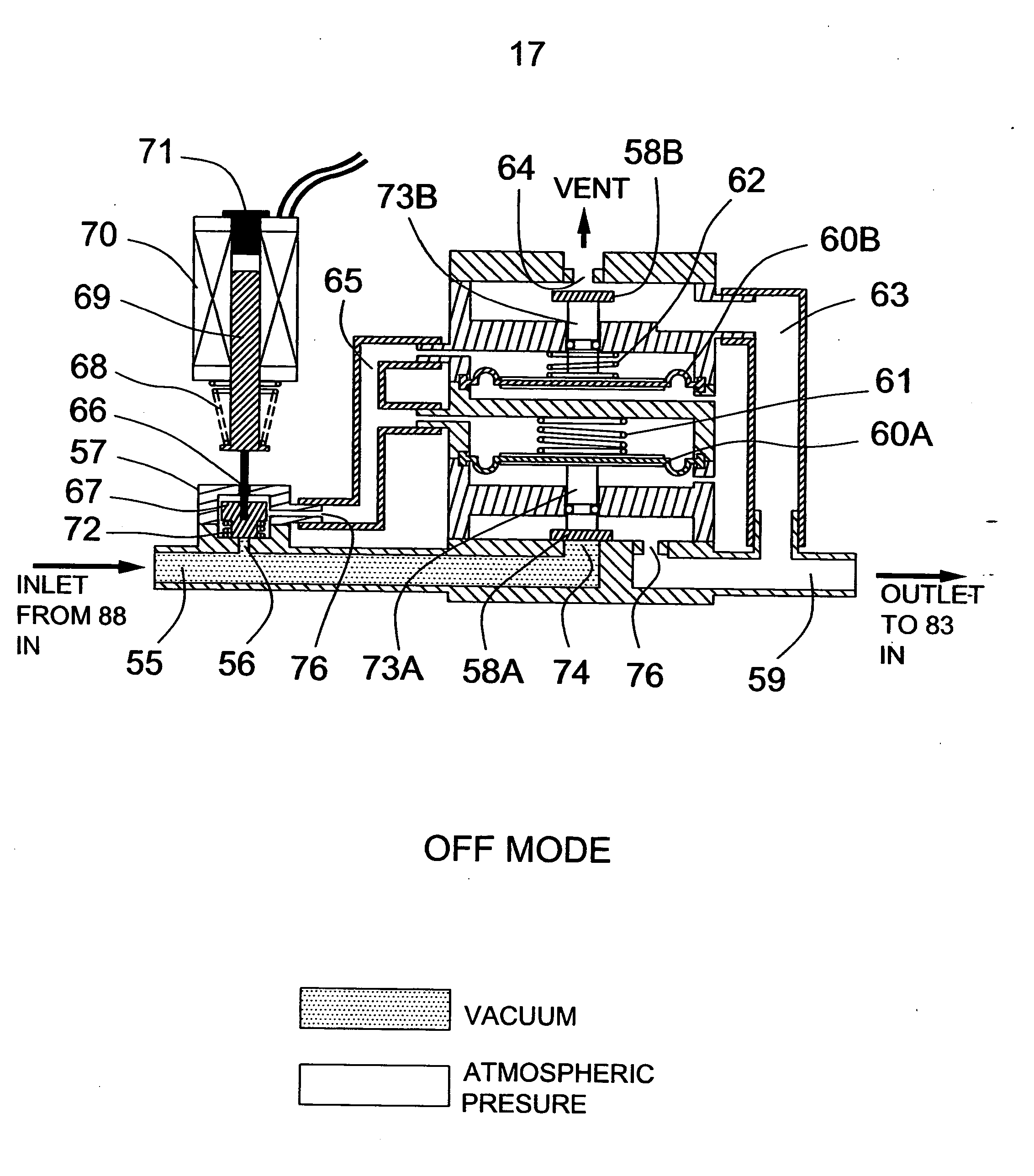
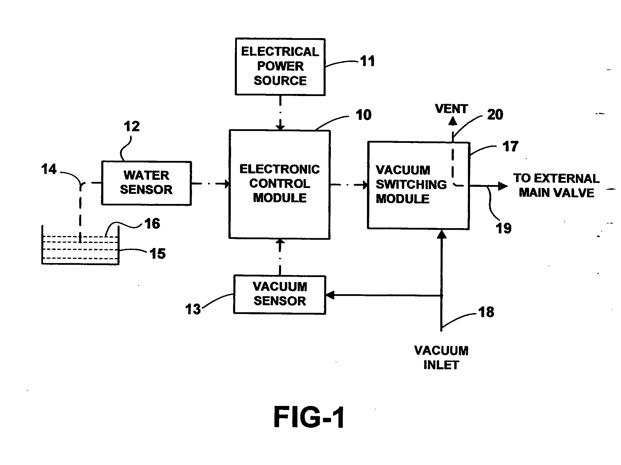
[0027] The apparatus comprises an electronic control module 10, a vacuum pressure sensor 13, a trigger switch 12, a vacuum switching module 17 and a means to electrically connect the electronic control module to a power source 11.

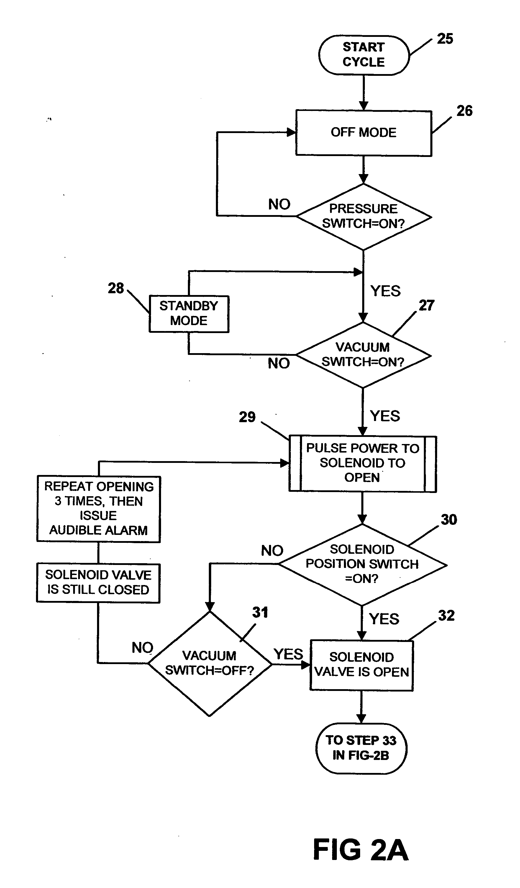
[0028] The electronic control module 10 is capable of storing an algorithm and receiving input data from at least one external source. The control module is capable of comparing the input data against a predetermined and stored algorithm and giving an output signal based upon the comparison of the input data to the algorithm.

[0029] The vacuum pressure sensor 13 is capable of sensing vacuum pressure present within a vacuum system to which the apparatus is fluidly connected. The vacuum pressure sensor is capable of sending output data and is functionally connected to allow input of vacuum ...


PUM


Abstract

An apparatus for controlling water flow is provided. The apparatus is a novel electronic water controller capable of operation using a battery-type power source, and providing for achievement of long battery life. The apparatus generally comprises an electronic control module, a vacuum pressure sensor, a trigger switch, a vacuum switching module and a means to electrically connect the electronic control module to a power source.

Description

CROSS-REFERENCE TO RELATED APPLICATIONS [0001] Not Applicable STATEMENT REGARDING FEDERALLY SPONSORED RESEARCH / DEVELOPMENT [0002] The present invention does not involve any form of federally sponsored research or development. BACKGROUND OF THE INVENTION [0003] The present invention relates to an apparatus for controlling water flow, namely a novel electronic water controller capable of operation using a battery-type power source. Currently available water controllers are mechanically operated and some applications can be powered using alternating current and direct current. [0004] Typically, water controllers are used in two primary applications. The first application is in water systems comprising a water overflow reservoir. An example of this application can be found in grocery stores. In grocery stores it is common to use refrigerators and freezers, as well as water “spritzers” used to keep produce fresh. Refrigerators and freezers generate condensate, and spritzers generate run-...

Claims


Application Information

Patent Timeline
Patent Type & Authority Applications(United States)
IPC IPC(8): G05D7/01
CPCG05D7/005Y10S137/907Y10T137/3109Y10T137/7761Y10T137/7762Y10T137/86389
Inventor TIWET, JOHN
Owner TIWET JOHN
Learn More