

Removal of contaminants from a fluid
- Summary
- Abstract
- Description
- Claims
- Application Information
AI Technical Summary
Benefits of technology
Problems solved by technology
Method used
Image

Examples
Embodiment Construction
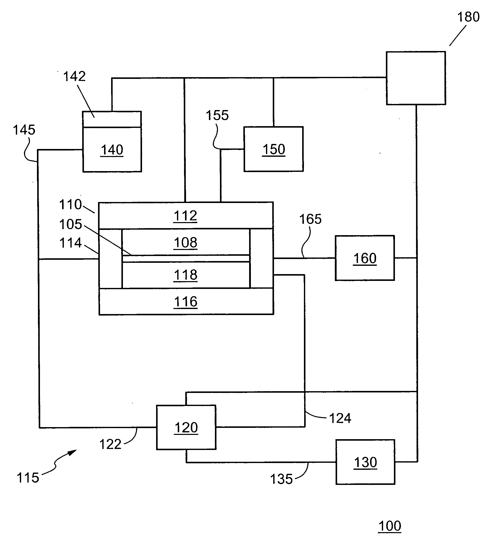
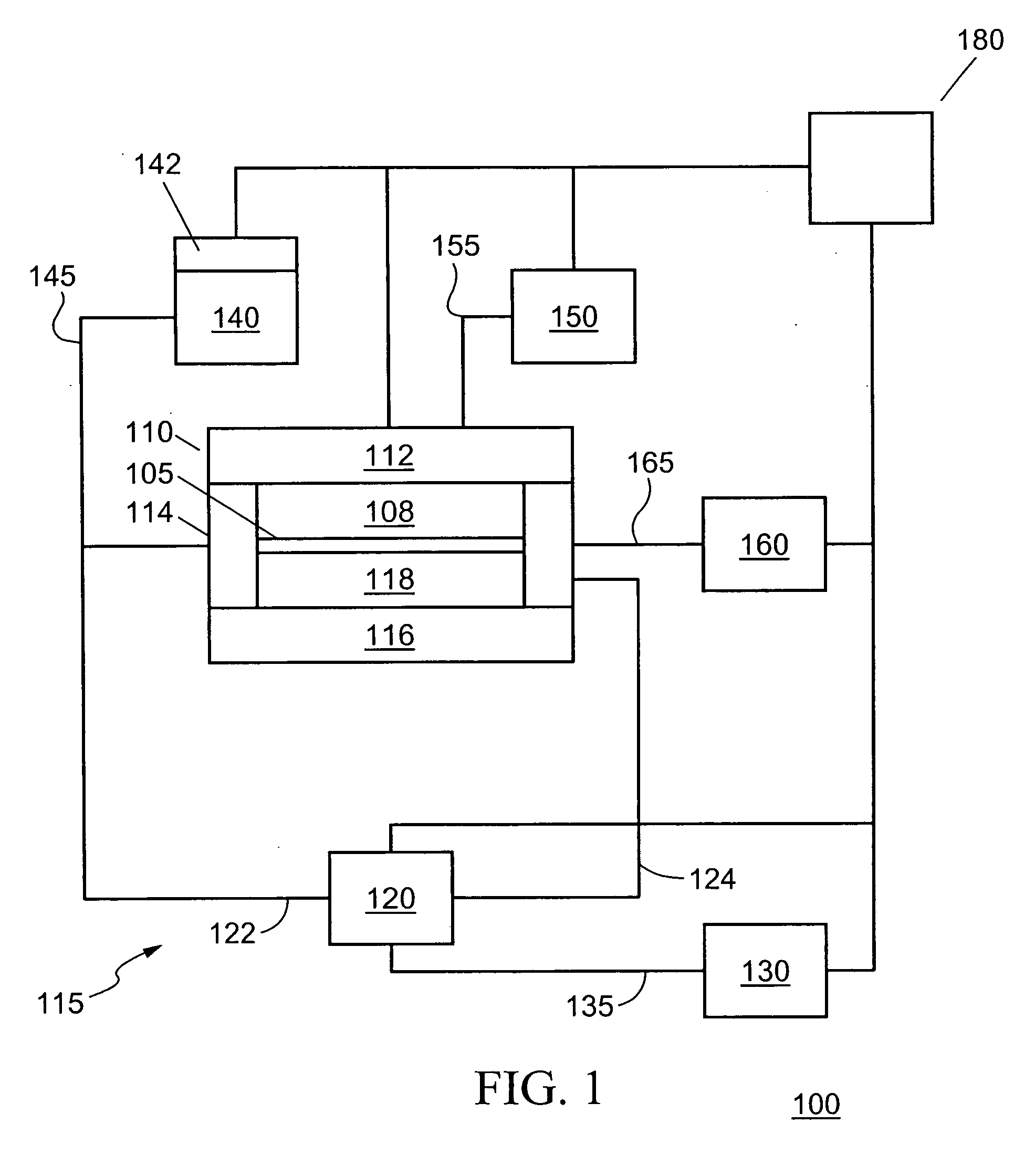
[0017] Semiconductor wafers that were cleaned using supercritical processing with commercially available CO2 revealed hydrocarbons and organic residues on the wafers. Hydrocarbons are commonly found as pump oils, lubricants and machining oils. It is known that thread sealant and lubricant on valves can be contributors to supercritical processing contamination. One approach to reducing the level of contamination in supercritical CO2 processing is to employ a system that addresses a more crucial and difficult problem, which is that the most probable source of supercritical CO2 processing contamination is the delivered CO2 itself. The present invention is directed to a method of removing contaminants from a fluid stream, such as a fluid stream of carbon dioxide.
[0018] For purposes of the invention, “carbon dioxide” should be understood to refer to carbon dioxide (CO2) employed as a fluid in a liquid, gaseous or supercritical (including near-supercritical) state. “Liquid carbon dioxide...
PUM
| Property | Measurement | Unit |
|---|---|---|
| Temperature | aaaaa | aaaaa |
| Temperature | aaaaa | aaaaa |
| Pressure | aaaaa | aaaaa |
Abstract
Description
Claims
Application Information