Removal of nitrogen dioxide from gas environments using metal-organic frameworks

a technology of metal-organic frameworks and nitrogen dioxide, which is applied in the direction of filtration separation, other chemical processes, separation processes, etc., can solve the problems of relative poor protection and removal capabilities of these gasses, and materials, however, suffer from several drawbacks, so as to reduce the concentration of nitrogen dioxide, reduce the amount of nitrogen dioxide in the sample, and reduce the level of a contaminant

Active Publication Date: 2018-01-16
UNITED STATES OF AMERICA
View PDF4 Cites 7 Cited by
  • Summary
  • Abstract
  • Description
  • Claims
  • Application Information

AI Technical Summary

Benefits of technology

[0007]The following summary of the invention is provided to facilitate an understanding of some of the innovative features unique to the present invention and is not intended to be a full description. A full appreciation of the various aspects of the invention can be gained by taking the entire specification, claims, drawings, and abstract as a whole.
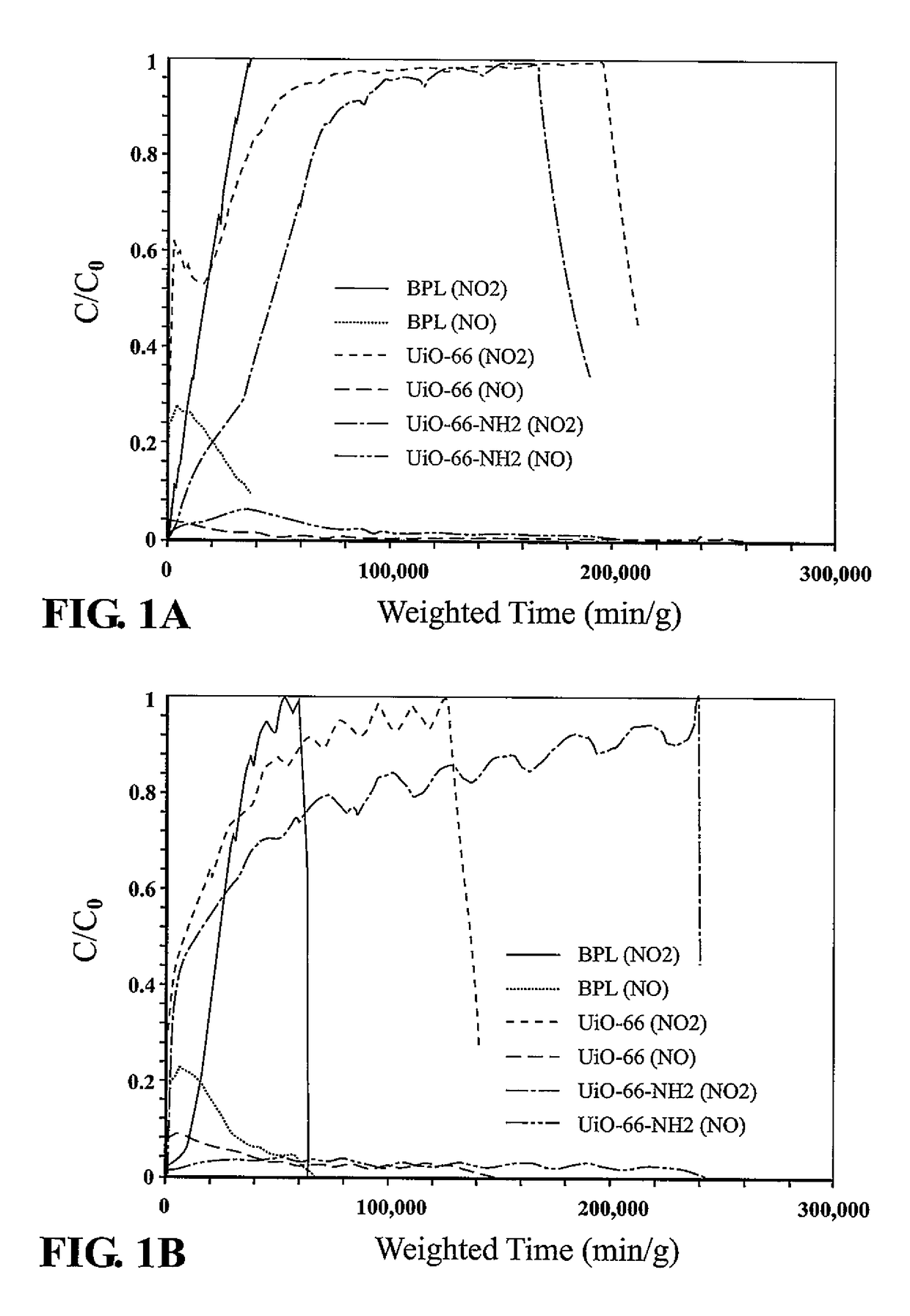
[0008]Provided are devices and methods for the filtration or other removal of nitrogen dioxide from a gaseous area or sample. A process in some aspects includes contacting or moving a gaseous sample comprising a nitrogen dioxide to or through a filter, surface, building material, or device comprising a filtration media, said filtration media comprising a metal organic framework (MOF), said filtration media suitable to react with the nitrogen dioxide, optionally to reduce the concentration of nitrogen dioxide in the gaseous sample thereby decreasing the amount of nitrogen dioxide in the sample. A MOF in some aspects includes a functional group capable of reacting with nitrogen dioxide, optionally an amine functional group. In some aspects the MOF includes or is UiO-66-NH2, optionally to the exclusion of other MOFs, or other filtration media, optionally with the proviso that the MOF is the only filtration media or combined with a carbon material, optionally activated carbon. A sample is optionally air or combustion exhaust. Illustrative MOFs optionally include a metal. A metal is optionally selected from the group of: Al, Cr, Fe, Hf, Mn, Ti, V, Zr, Ca, and Mg. Optionally, a metal is Zr alone, Ti alone, or combinations thereof with no other metal in the MOF. In some aspects, a MOF has an average pore volume of 0.1 cm3 / g or greater. Optionally, the MOF has a surface area in excess of 600 m2 / g as measured by a Brunauer Emmett Teller (BET) technique. Optionally, the MOF has a capacity for absorbing nitrogen dioxide of 9 moles NO2 per kilogram MOF or greater. A process is optionally performed at a temperature of 20° C. to 30° C., but optionally may be performed at elevated temperatures, optionally up to 400° C. In some aspects, an MOF is combined with a second MOF, a second other filter material, or both. A filter material optionally includes carbon, optionally an activated carbon. In some aspects, a filter is a building material.
[0009]Also provided are devices for reducing the level of a contaminant in a gas. In some aspects a device is a filter capable of reducing nitrogen dioxide in sample, an environmental area, or a flow of gas, optionally at a temperature of 10 degrees Celsius to 50 degrees Celsius. A device optionally includes an amine modified porous metal organic framework (MOF), the MOF comprising a metal selected from the group consisting of Zr and Ti, and a carbon filtration media. The MOF optionally has an average pore volume of 0.1 cm3 / g or greater. The MOF optionally has a surface area in excess of 600 square meters per gram as measured by a Brunauer Emmett Teller (BET) technique. In some aspects, the MOF used in the filter has a capacity for absorbing nitrogen dioxide of 9 moles per kilogram or greater. The MOF is optionally located within the filter adjacent to the carbon filtration media, optionally directly adjacent to the carbon filtration media, optionally intermixed with the carbon filtration media. In some aspects, the MOF is directly on the carbon filtration media proximal to a nitrogen dioxide source.

Problems solved by technology

The common respirators available to these individuals, which typically rely on activated carbon as a filtration media, provide relatively poor protection and removal capabilities for these gasses.
These materials, however, suffer from several drawbacks.

Method used


Image

  • Removal of nitrogen dioxide from gas environments using metal-organic frameworks
  • Removal of nitrogen dioxide from gas environments using metal-organic frameworks
  • Removal of nitrogen dioxide from gas environments using metal-organic frameworks

Examples


Embodiment Construction

[0021]The following description of particular aspect(s) is merely exemplary in nature and is in no way intended to limit the scope of the invention, its application, or uses, which may, of course, vary. The invention is described with relation to the non-limiting definitions and terminology included herein. These definitions and terminology are not designed to function as a limitation on the scope or practice of the invention but are presented for illustrative and descriptive purposes only. While the processes or compositions are described as an order of individual steps or using specific materials, it is appreciated that steps or materials may be interchangeable such that the description of the invention may include multiple parts or steps arranged in many ways as is readily appreciated by one of skill in the art.

[0022]It will be understood that, although the terms “first,”“second,”“third” etc. may be used herein to describe various elements, components, regions, layers, and / or sec...


PUM

PropertyMeasurementUnit
reaction temperatureaaaaaaaaaa
temperaturesaaaaaaaaaa

Abstract

Provided are materials and processes for removing nitrogen dioxide gas from a sample by contacting the sample with a filtration media that includes a MOF, optionally an amine containing MOF. The resulting filtration media has the ability to sequester nitrogen dioxide with little conversion to nitric oxide, is stable, and highly functional so as to be useful in protective equipment or other filtration systems.

Description

REFERENCE TO RELATED APPLICATIONS[0001]This application claims the benefit of and priority from U.S. Provisional Application Ser. No. 62 / 306,229 filed on Mar. 10, 2016.U.S. GOVERNMENT INTEREST[0002]The invention described herein may be manufactured, used and licensed by or for the U.S. Government.FIELD[0003]This invention relates generally to air filtration and filtration media.BACKGROUND[0004]Various vehicles and industries, including those involving coal-fired electrical power generation, wood processing, and oil and gas production, produce nitrogen oxide gases (e.g., NO, N2O, NO2, and N2O4). Nitrogen oxides (collectively referred to as NOx), and particularly, nitrogen dioxide, are primary air pollutants and among the most common toxic pollutants generated on earth. The continual generation of such materials provokes considerable interest in the development of efficient, cost effective technologies to remediate NOx-containing emissions such as in flue gas scrubbing operations, in ...

Claims


Application Information

Patent Timeline
Patent Type & Authority Patents(United States)
IPC IPC(8): B01D53/56B01D46/00B01D39/00C07F3/02B01J20/22B01J8/02C01C1/12C07F15/02C07F11/00C07F7/28C07F5/06C07F3/04
CPCB01J20/226B01J8/02C01C1/12C07F15/02C07F11/00C07F7/28C07F5/06C07F3/04C07F3/02B01D53/02B01J20/28069B01J20/28057B01D2253/102B01D2253/1122B01D2253/204B01D2253/306B01D2253/311B01D2257/404B01D2258/0283B01D2258/06B01D2259/4541B01D2259/4591B01D39/2055Y02A50/20
Inventor PETERSON, GREGORY W
Owner UNITED STATES OF AMERICA
Why Eureka
Try Eureka