
Beverage refrigerator

Inactive Publication Date: 2006-09-28
LG ELECTRONICS INC
View PDF11 Cites 86 Cited by
  • Summary
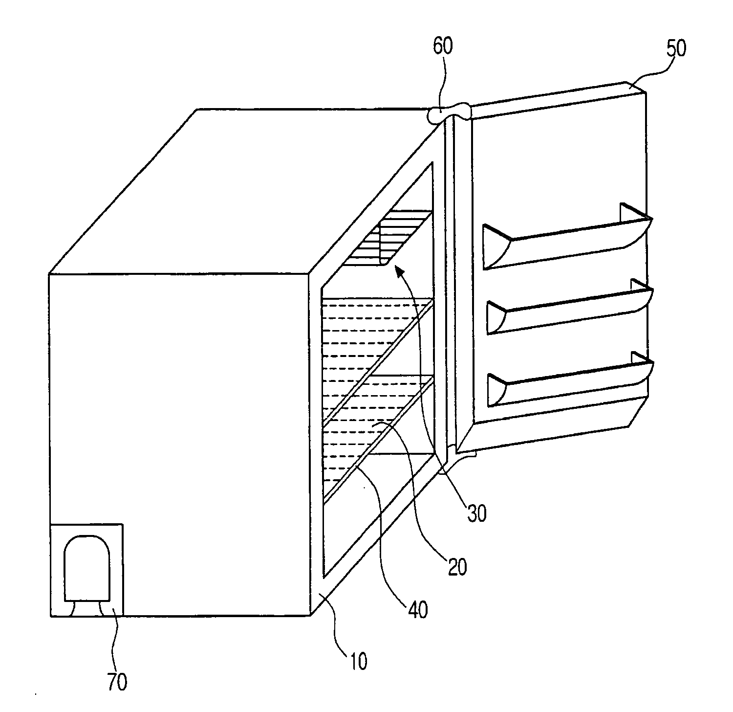
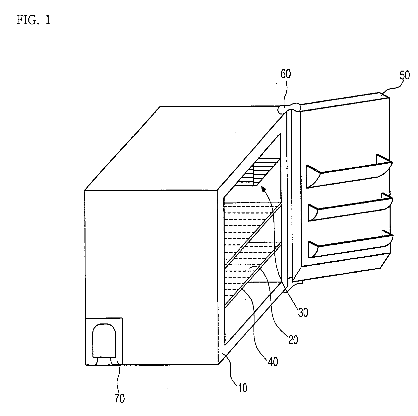
  • Abstract
  • Description
  • Claims
  • Application Information

AI Technical Summary

Benefits of technology

[0016] Accordingly, the present invention has been made to solve the above-mentioned problems occurring in the prior art, and an object of the present invention is to provide a beverage refrigerator, which can improve the efficiency in cold storage of beverages.
[0017] It is another object of the present invention to provide a beverage refrigerator, which enables a user to more easily put in or take out a beverage from the refrigerator.
[0018] It is another object of the present invention to provide a beverage refrigerator, which has a structure capable of improving the heat discharge efficiency of the elements housed in a machine room of the refrigerator.
[0019] It is another object of the present invention to provide a beverage refrigerator, which has a structure for more efficient utilization of the storage space in the refrigerator.
[0020] It is another object of the present invention to provide a beverage refrigerator, which can achieve more efficient utilization of the top surface of the refrigerator.
[0022] The beverage refrigerator according to the present invention can improve the efficiency in cold storage of beverages, enables a user to more easily put in or take out a beverage from refrigerator, improves the heat discharge efficiency of the elements housed in a machine room of the refrigerator, and can achieve more efficient utilization of the top surface of the refrigerator.

Problems solved by technology

However, the conventional beverage refrigerator as described above has the following problems:
Therefore, it is difficult to effectively discharge the heat generated by the operation of the elements constituting the cooling cycle housed in the machine room 70.
Therefore, it may be impossible to put a large beverage container or package (for example, a beverage pack containing multiple cans or bottles) in the lower part or compartment of the storage space 20.
Therefore, the machine room 70 located at the rear lower part of the conventional beverage refrigerator may increase the users' difficulty or inconvenience in putting beverage in or out of the storage space 20.
Therefore, the top surface of the refrigerator body 10 may be higher or lower than the height of other pieces of furniture, so that it may be difficult to effectively use the top surface of the refrigerator body 10.

Method used


Image

  • Beverage refrigerator
  • Beverage refrigerator
  • Beverage refrigerator

Examples


Embodiment Construction

[0027] Hereinafter, a beverage refrigerator according to a preferred embodiment of the present invention will be described in detail with reference to the accompanying drawings.

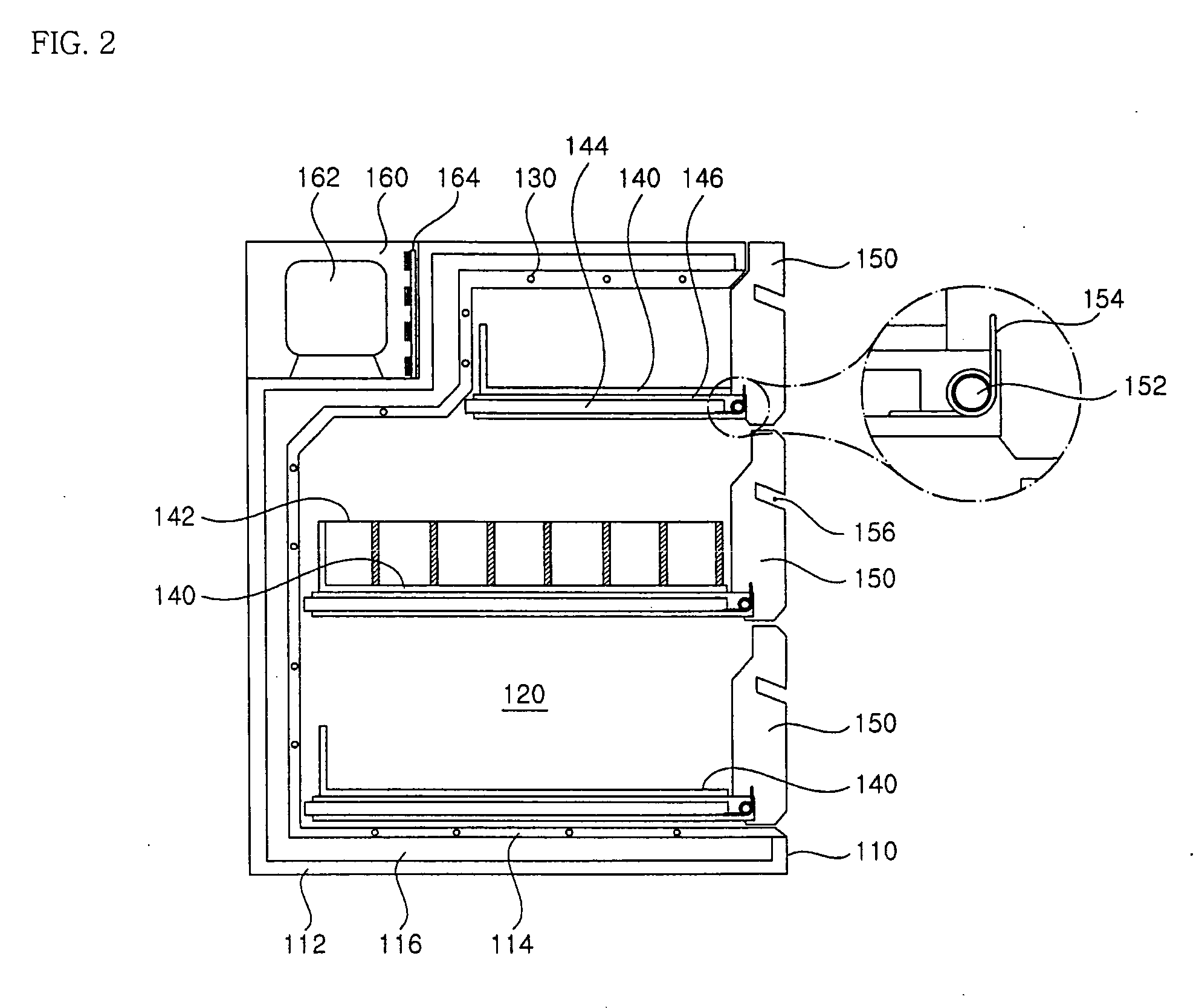
[0028]FIG. 2 illustrates a beverage refrigerator according to a preferred embodiment of the present invention.

[0029] As shown, a refrigerator body 110 of the beverage refrigerator includes an outer case 112 and an inner case 114, which form inner and outer appearances, respectively. An adiabatic layer 116 is disposed between the outer case 112 and the inner case 114.

[0030] The refrigerator body 110 may have various dimensions, which include a height corresponding to the height of various pieces of furniture. For example, the refrigerator body 110 may be designed to have a height of 65 or 75 cm, which are standards for typical household furniture, or a height of 85 or 95 cm, which are standards for typical kitchen furniture.

[0031] The refrigerator body 110 has a storage space 120 defined in the refrigerato...


PUM


Abstract

A beverage refrigerator includes: a refrigerator body having a predetermined storage space surrounded by an evaporator; one or more beverage carriages, each of which is pushed into and drawn out of the storage space like a drawer, and on each of which beverages are stored; and as many doors as the beverage carriages, each of which has a first end hingedly assembled with a corresponding beverage carriage and a second end pivotable about the first end, so as to selectively open and close the storage space.

Description

BACKGROUND OF THE INVENTION [0001] 1. Field of the invention [0002] The present invention relates to a refrigerator, and more particularly to a beverage refrigerator for storing cans or bottles containing beverages or drinks. [0003] 2. Description of the Prior Art [0004] As used herein, a beverage refrigerator refers to a small refrigerator which is used in hotel rooms or offices, etc., in order to store beverages. [0005]FIG. 1 illustrates a conventional beverage refrigerator. [0006] As shown, a refrigerator body 10 has a storage space 20 for storing beverages, which is defined in the refrigerator body 10. An evaporator 30 is disposed at one side in the storage space 20. The storage space 20 is directly cooled by the evaporator 30. [0007] Shelves 40 are disposed in the storage space 20, to partition the storage space 20 into several compartments, thereby improving the efficiency in use of the storage space 20. [0008] A door 50 is rotatably assembled with one side of the refrigerator...

Claims


Application Information

Patent Timeline
IPC IPC(8): A47F5/08
CPCE05Y2900/31F25D23/003F25D25/021F25D25/025F25D2323/00262F25D2323/00278F25D2323/024F25D2331/803F25D2331/805F25D2331/809F25D2400/08F25D11/00F25D25/00
Inventor KWON, YONG CHOL
Owner LG ELECTRONICS INC
Learn More