Engine generator

a generator and engine technology, applied in the field of generator sets, can solve the problems of difficult to achieve the accuracy of the mounting position of such members etc., and achieve the effect of smooth air flow, increase the number of such members, and smooth guide cooling air

Inactive Publication Date: 2006-09-28
YAMAHA MOTOR POWER PROD KK
View PDF10 Cites 32 Cited by
  • Summary
  • Abstract
  • Description
  • Claims
  • Application Information

AI Technical Summary

Benefits of technology

[0007] An aspect of at least one of the embodiments disclosed herein includes the realization that forming cooling air guides so as to smoothly guide cooling air around an engine, a generator, and a muffler of the engine can be difficult. For example, such known generator sets have housings made from multiple pieces, some of which have portions of the air guides, and which form the complete...

Problems solved by technology

This results in complex shapes of the respective members forming the cooling air guides, and increases the number of suc...

Method used


Image

  • Engine generator
  • Engine generator
  • Engine generator

Examples


Embodiment Construction

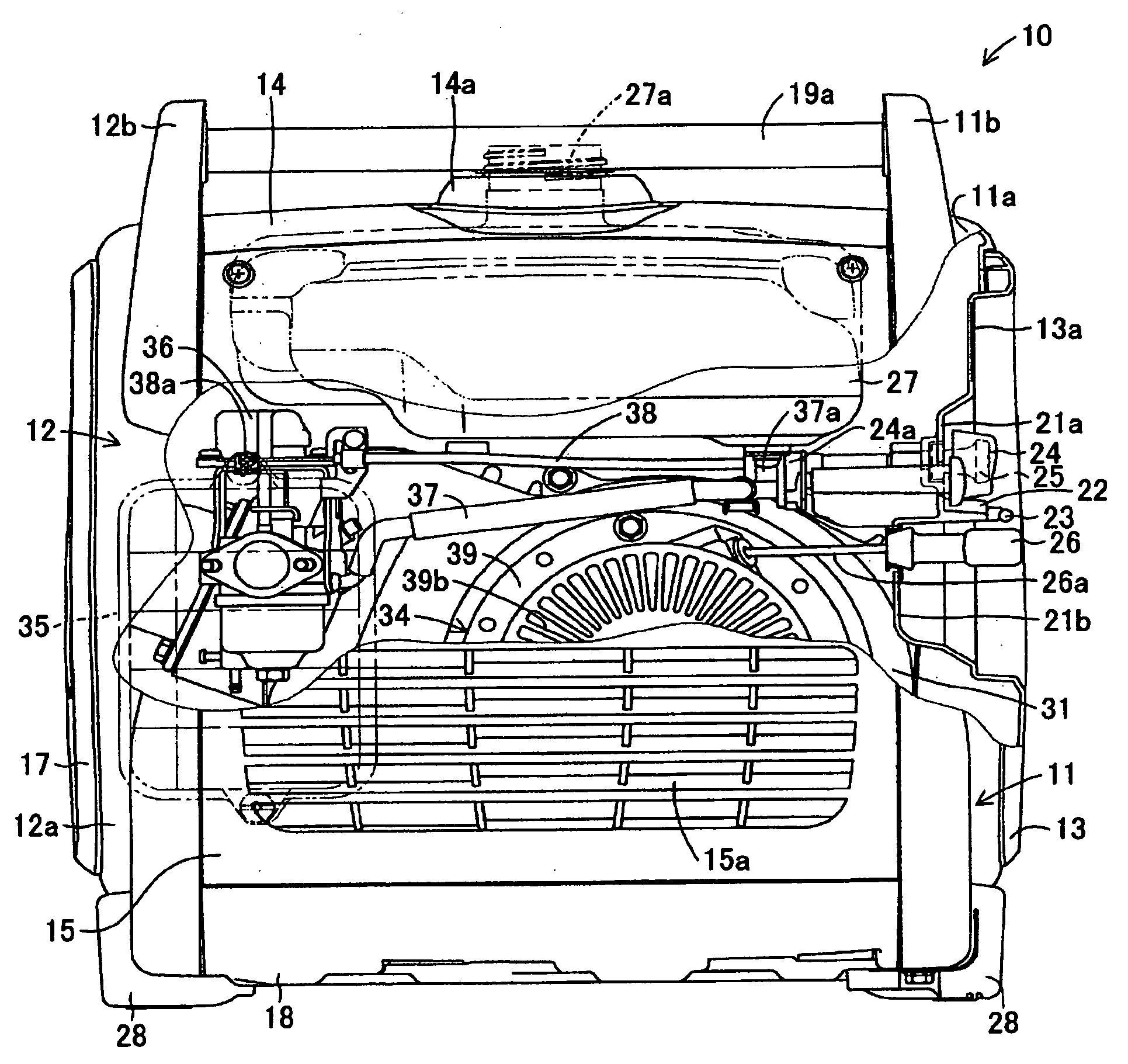
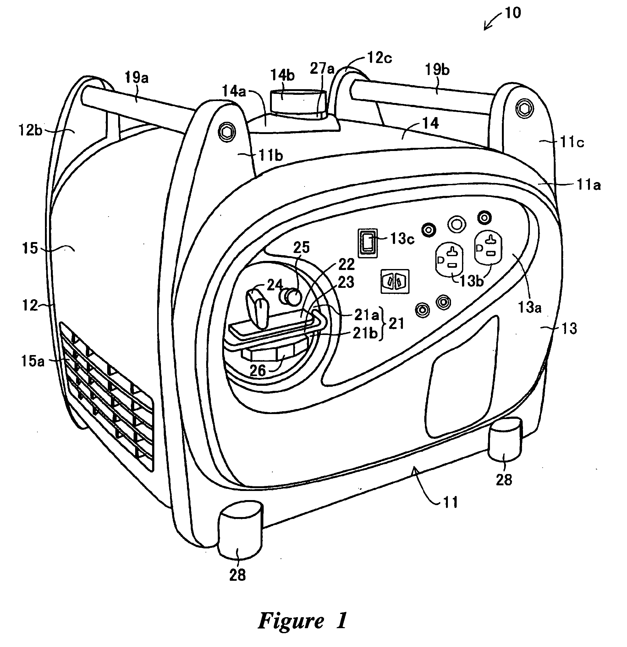
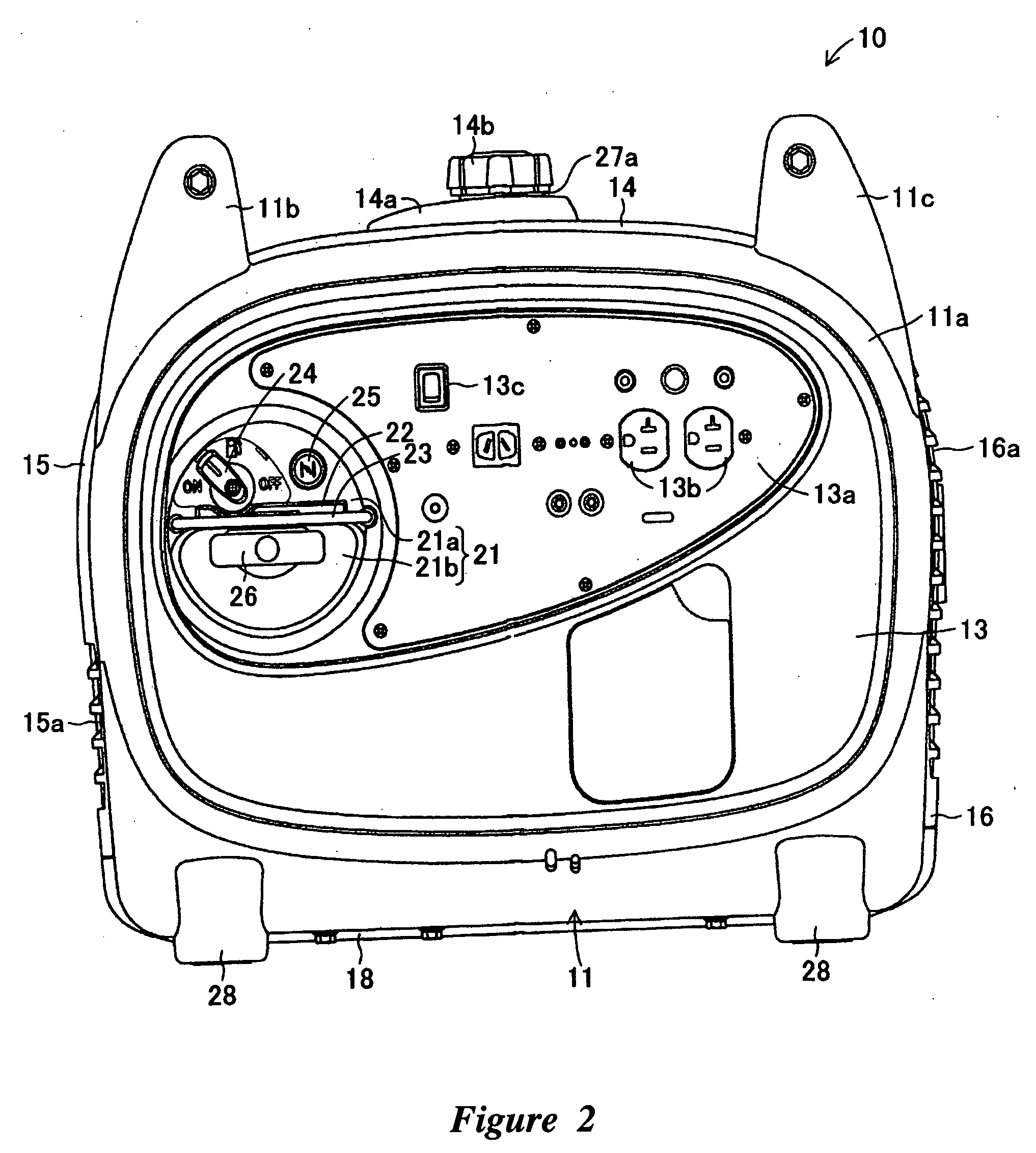
[0023] An engine generator 10 in accordance with various embodiments of the present inventions is described below with reference to drawings. The embodiments of the cooling system of the generator 10 are described in the context of an engine generator because they have particular utility in this context. However, the cooling systems disclosed herein can be used in other contexts, such as, for example, any device that utilizes air cooling.

[0024]FIGS. 1 through 5 show an engine generator 10 according to an embodiment. The outer surface of the engine generator 10 can be formed in a rounded, generally box shape. The generator 10 can include a pair of front and rear frames 11, 12 spaced apart from each other in the forward and rearward directions, a front panel 13 and a rear panel 17 located within the front frame 11 and the rear frame 12, respectively. Additionally, a top panel 14, an intake cover 15, an exhaust cover 16 and a bottom panel 18 can be located between the front frame 11 a...


PUM


Abstract

An engine generator can have an engine duct for releasing to the outside a cooling air which is used to cool an engine and a muffler, and a generator duct for releasing to the outside a cooling air which is sued to cool a generator. The engine duct and the generator duct can be formed in one body as an exhaust duct. The muffler and the generator can be laterally aligned in parallel with each other, and the engine duct and the generator duct can be located in a manner such that the directions of release of the cooling winds from the engine duct and the generator duct are parallel to each other. The exhaust duct can be located with the generator duct secured to a crankcase. An opening of the engine duct, and an opening of the generator duct can be laterally aligned with each other, and the opening of the generator duct can be positioned above the generator.

Description

PRIORITY INFORMATION [0001] This application is based on and claims priority under 35 U.S.C. § 119 to Japanese Patent Application No. 2005-001429, filed on Jan. 6, 2005, the entire contents of which is hereby expressly incorporated by reference. BACKGROUND OF THE INVENTIONS [0002] 1. Field of the Inventions [0003] The present inventions relate to generator sets, and more particularly, the cooling systems of generator sets. [0004] 2. Description of the Related Art [0005]“Engine generators” or “generator sets” usually have an engine driving a generator to generate electrical power. Some of such generator sets include an air cooling arrangement which includes guide members configured to guide cooling air to cool the engine and the generator. For example, Japanese Patent Document JP-A-Hei 7-312846 includes such an arrangement. [0006] The generator set disclosed in JP-A-Hei 7-312846 includes two fans, one for directing ambient air toward the engine and the other for directing ambient air...

Claims


Application Information

Patent Timeline
IPC IPC(8): H02K7/18F02B63/00
CPCF01P1/02F01P2005/025F02B63/04F02B63/048H02K7/1815H02K9/06
Inventor YAMAMOTO, MASANOBUSUGIYAMA, TAKAHIDE
Owner YAMAHA MOTOR POWER PROD KK
Why Eureka
Try Eureka