Discharge tube operation device

Inactive Publication Date: 2006-09-28
SANKEN ELECTRIC CO LTD
View PDF7 Cites 4 Cited by
  • Summary
  • Abstract
  • Description
  • Claims
  • Application Information

AI Technical Summary

Benefits of technology

[0034] The present invention was made in view of the above circumstance, and an object of the present invention is to provide a discharge tube operation device which can achieve a desired illuminance while also suppressing occurrence of a surge.
[0035] Another object of the present invention is to provide a discharge tube operation device which can secure a sufficient lit period in order to achieve a desired illuminance while also suppressing occurrence of a surge.
[0043] By employing such a configuration, a desired illuminance can be obtained while occurrence of a surge is suppressed. Further, a sufficient lit period for obtaining a desired illuminance can be obtained while occurrence of a surge is suppressed.
[0046] By employing such a configuration, it is possible to provide a discharge tube operation device capable of obtaining a desired illuminance while suppressing occurrence of a surge. Further, it is possible to provide a discharge tube operation device capable of obtaining a sufficient lit period for obtaining a desired illuminance while suppressing occurrence of a surge.

Problems solved by technology

The occurrence of this surge will be a cause of shortening the life of the discharge tube 63.

Method used


Image

  • Discharge tube operation device
  • Discharge tube operation device
  • Discharge tube operation device

Examples


first embodiment

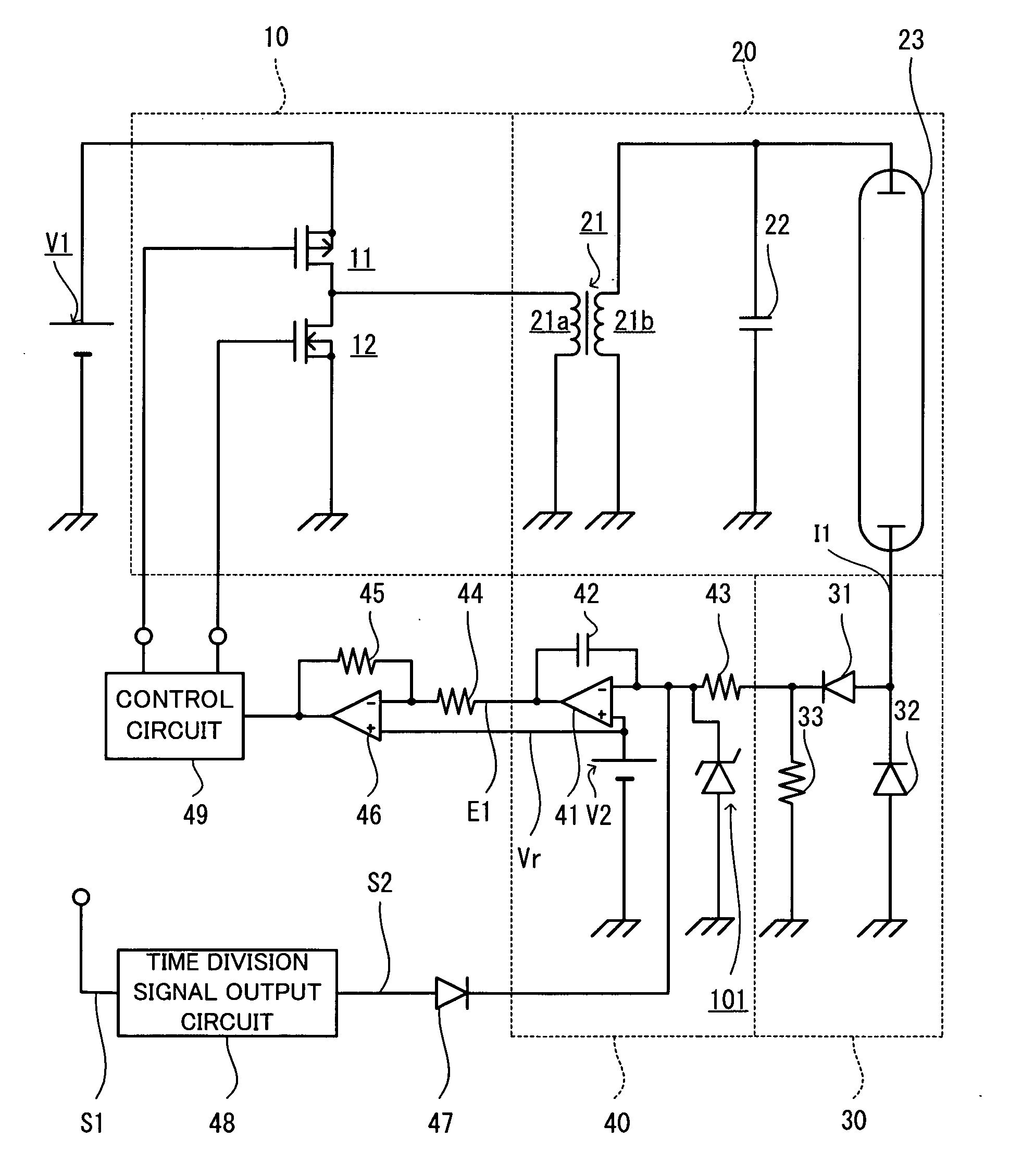
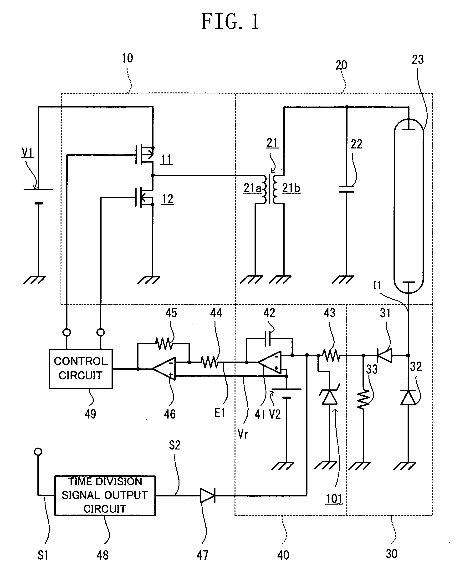
[0054]FIG. 1 is a block diagram of a discharge tube operation device according to the first embodiment of the present invention.

[0055] This discharge tube operation device comprises a direct-current power source V1, a DC-AC conversion circuit 10, a resonance circuit 20, a discharge tube current detection circuit 30, an integration circuit 40, a subtractor 46, a time division signal output circuit 48, and a control circuit 49.

[0056] The direct-current power source V1 is a power source that supplies a direct-current voltage to the DC-AC conversion circuit 10, and its negative electrode (−) is earthed while its positive electrode (+) is connected to the DC-AC conversion circuit 10.

[0057] The DC-AC conversion circuit 10 comprises a MOSFETs 11 and 12 functioning as switching elements. The MOSFETs 11 and 12 form a complementary circuit and are connected between the direct-current power source V1 and the ground.

[0058] The DC-AC conversion circuit 10 converts a direct-current voltage in...

second embodiment

[0106]FIG. 3 is a block diagram of a discharge tube operation device according to the second embodiment of the present invention.

[0107] The control circuit 49 of a frequency varying type is used in the first embodiment, but a control circuit 49b of a PWM (Pulse Width Modulation) control type may be used.

[0108] Since the discharge tube operation device has a similar configuration to the first embodiment, the same elements as in FIG. 1 will be given the same reference numerals, and only the matters that are different from the first embodiment will be explained and explanation for the others will be omitted.

[0109] With such a configuration, the control circuit 49b outputs a duty ratio control signal for controlling the duty ratio of the output from the MOSFETs 11 and 12. Since the voltage to be applied to the resonance circuit 20 is controlled by the duty ratio control signal, the current I1 that will flow through the discharge tube 23 is controlled. The time division signal output ...


PUM


Abstract

A time division signal (S2) for instructing a lit period and an unlit period of a discharge tube (23) is input to an error amplifier (41) of an integration circuit (40). The integration circuit (40) charges and discharges a capacitor (42) in accordance with the time division signal (S2). By utilizing this operation, a control circuit (49) adjusts a current flowing through the discharge tube (23) to light and extinguish the discharge tube (23).

Description

TECHNICAL FIELD [0001] The present invention relates to a discharge tube operation device which adjusts the illuminance of a discharge tube by adjusting a current flowing through the discharge tube. BACKGROUND ART [0002] Among discharge tube operation devices used in liquid crystal backlights, etc., there are such devices that adjust the illuminance of the discharge tube by adjusting a current flowing through the discharge tube by feedback-controlling the current in the discharge tube, as disclosed in, for example, Unexamined Japanese Patent Application KOKAI Publication No. 2002-43088. [0003] The general configuration of a conventional discharge tube operation device of this type is illustrated in FIG. 4. The conventional discharge tube operation device comprises a direct-current power source V3, a DC-AC(direct-current-alternating-current) conversion circuit 50, a resonance section 60, a discharge tube current detection circuit 70, a soft-start circuit 80, an error amplifier 83, a ...

Claims


Application Information

Patent Timeline
IPC IPC(8): H05B41/36H05B39/04H05B41/392
CPCY10S315/04H05B41/3927H05B41/38
Inventor KIMURA, KENGOASHIKAGA, TORU
Owner SANKEN ELECTRIC CO LTD
Why Eureka
Try Eureka