Optical droplet sensor and method

Inactive Publication Date: 2006-09-28
STANLEY ELECTRIC CO LTD
View PDF3 Cites 20 Cited by
  • Summary
  • Abstract
  • Description
  • Claims
  • Application Information

AI Technical Summary

Benefits of technology

[0017] The optical droplet sensor is installed on one surface of the light transmissive structure to detect droplets attached on another surface thereof. A light guide contained in the optical raindrop sensor can include a light entry surface formed of an arbitrary curved convex surface with an optimized light distribution characteristic for introducing the light emitted from the light emitter into the light guide. It also has a light exit surface that can be formed of an arbitrary curved convex surface with an optimized light distribution characteristic for releasing/emitting the light guided through the light guide outward from the light guide and focusing the light on the light receiver. Therefore, optimization of a droplet detection range on the light transmissive structure and enhanced efficiency of collection of light to the light receiver can improve the accuracy of detection of droplets.
[0018] The reflector surfaces can include a metal film-applied reflecting surface provided on the light guide for changing the direction of light traveling through the light guide. Accordingly, it is possible to prevent light from leaking outward

Problems solved by technology

In this case, however, the shape/size of the raindrop sensor in the direction of the length disadvantageously becomes larger.
In addition,

Method used


Image

  • Optical droplet sensor and method
  • Optical droplet sensor and method
  • Optical droplet sensor and method

Examples


Example

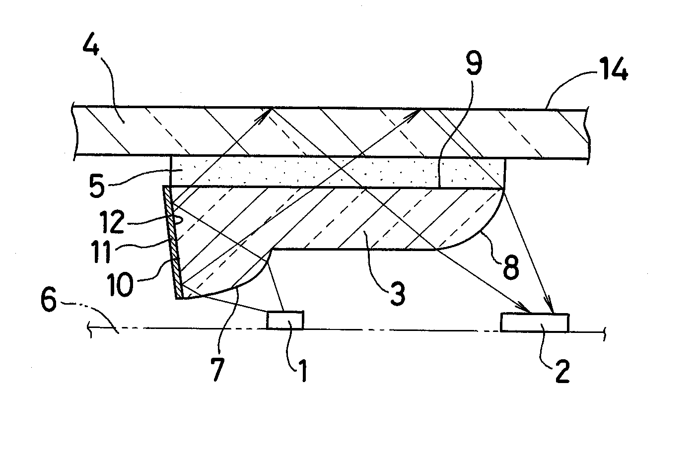
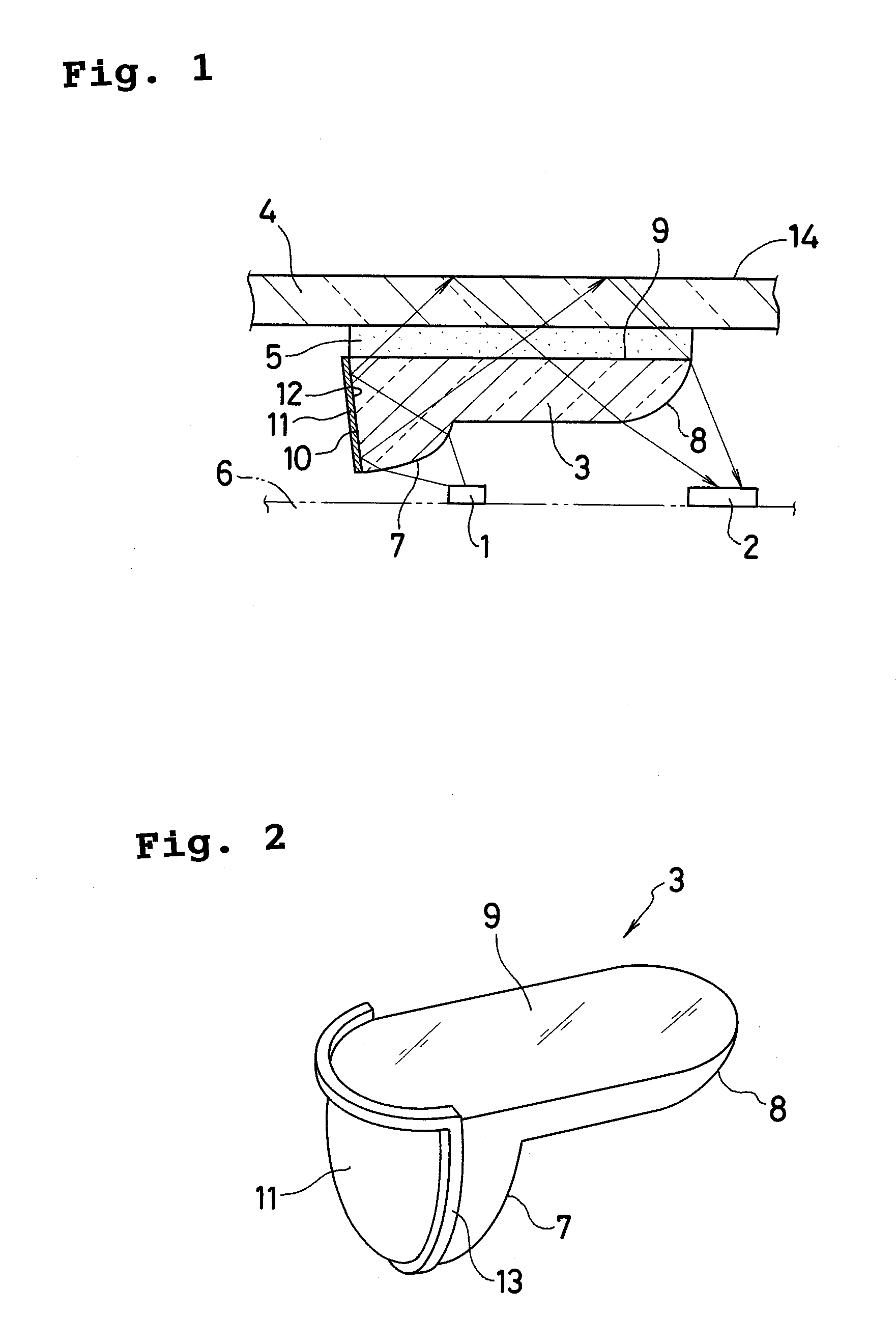
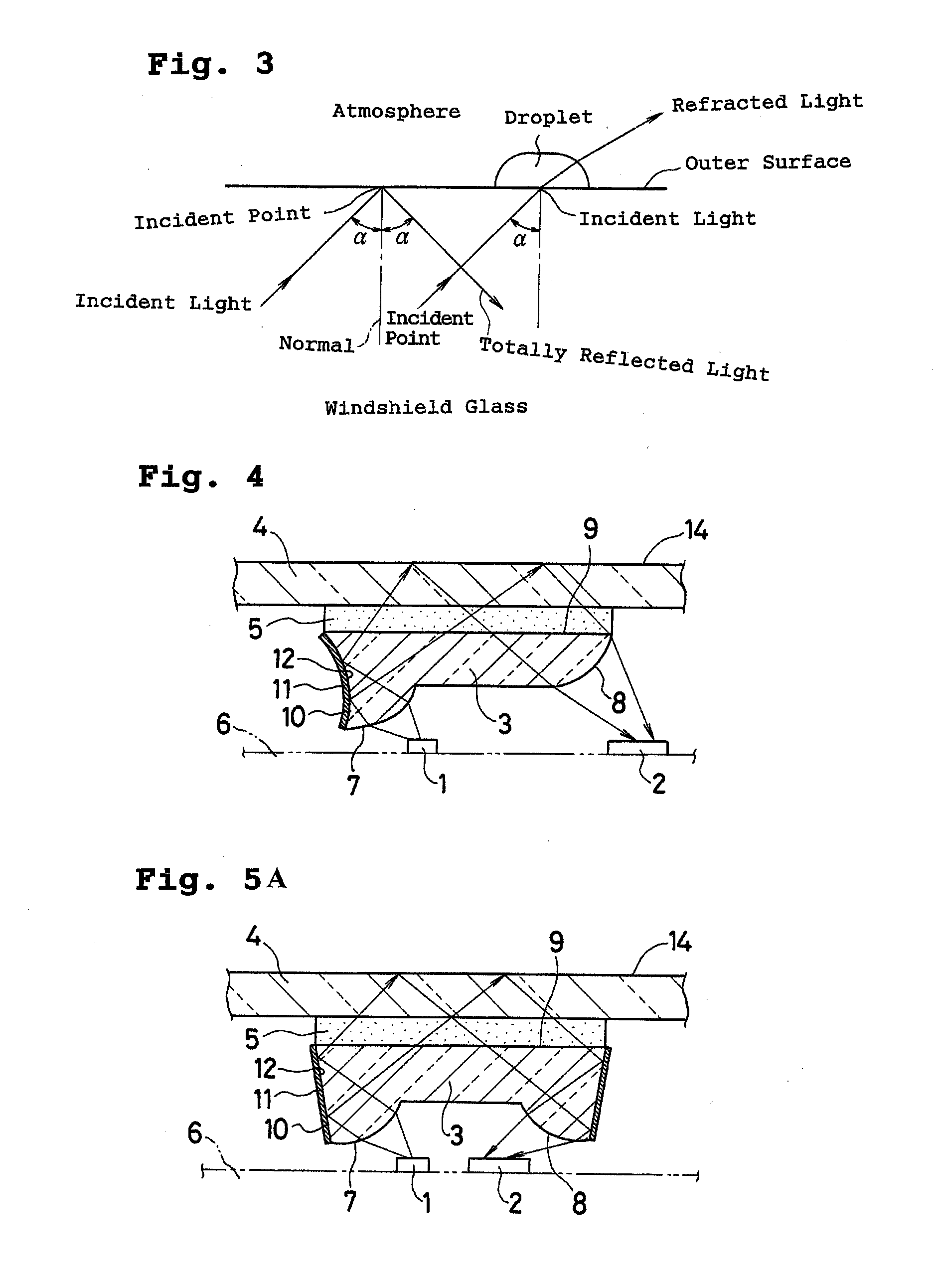
[0027] An optical droplet sensor capable of being downsized and having high flexibility of design and high accuracy of detection can be achieved as follows. A light guide contained in the optical raindrop sensor can include a light entry surface formed of an arbitrary curved convex surface with an optimized light distribution characteristic for introducing the light emitted from the light emitter into the light guide. A light exit surface can be formed of an arbitrary curved convex surface with an optimized light distribution characteristic for releasing / transmitting the light guided through the light guide outward from the light guide and focusing the light on the light receiver. Further, the sensor can include a reflecting surface, such as a metal film-applied reflecting surface, provided on the light guide for changing the direction of light traveling through the light guide.

[0028] Exemplary embodiments of the disclosed subject matter will now be described in detail with referen...


PUM


Abstract

An optical droplet sensor can include a light emitter, a light receiver and a light guide, and can be adhered onto an inner surface of a windshield via a light transmissive adhesive layer. The light guide can include a light entry surface and a light exit surface formed of respective convex-shaped arbitrary curved surfaces, a light entry/exit surface formed of a flat plane, and a reflecting surface that can be made of a metal film. The light emitted from the light emitter is given an optimized light distribution at the light entry surface and introduced into the light guide. The light is then reflected from the metal film-applied reflecting surface toward an outer surface of the windshield. The light totally reflected at the outer surface returns to the light exit surface and is given an optimized light distribution at the light exit surface. The light is then externally transmitted/released from the light guide and collected on a light-receiving surface of the light receiver.

Description

[0001] This application claims the priority benefit under 35 U.S.C. §119 of Japanese Patent Application No. 2005-082153 filed on Mar. 22, 2005, which is hereby incorporated in its entirety by reference. BACKGROUND [0002] 1. Field [0003] The disclosed subject matter relates to an optical droplet sensor and method capable of optically detecting droplets attached to a surface of a light transmissive structure, for example, a windshield plate. [0004] 2. Description of the Related Art [0005] An optical droplet sensor is conventionally installed on an inner surface of a windshield of a vehicle and detects droplets attached on an outer glass surface thereof for automatically operating wipers to ensure a fine view while driving in rain. An example of such an optical droplet sensor is described as follows. [0006] This conventional sensor includes a beam transmitter 50 and a beam receiver 51 mounted on a printed circuit board 52 as shown in FIG. 6 such that respective optical axes in exit and...

Claims


Application Information

Patent Timeline
IPC IPC(8): G01N21/55B60S1/08G01N21/17
CPCB60S1/0822B60S1/0837G01N21/552
Inventor TAKATA, HIROSHIISHIKAWA, KIYOMITSUYOKOYAMA, YORIMI
Owner STANLEY ELECTRIC CO LTD
Why Eureka
Try Eureka