
Distance measurement apparatus, electronic device, distance measurement method, distance measurement control program and computer-readable recording medium

a technology of distance measurement and control program, which is applied in the direction of distance measurement, instruments, surveying and navigation, etc., can solve the problems of large amount of computation, decrease in accuracy of computation, and increase in the cost of the distance measurement apparatus, so as to facilitate and accelerate processing, the effect of facilitating and rapid processing

Inactive Publication Date: 2006-09-28
SHARP KK
View PDF1 Cites 18 Cited by
  • Summary
  • Abstract
  • Description
  • Claims
  • Application Information

AI Technical Summary

Benefits of technology

[0014] The present invention is made to solve the problems described above. The objective of the present invention is to provide: a distance measurement apparatus capable of determining (detecting) a distance between an object to be imaged and an image capturing apparatus by performing a simple image processing without requiring two or more image capturing apparatuses or without the necessity to know the size of the object to be imaged; an electronic device (e.g. a vacuum clear running randomly in a room or a surveillance camera) having the distance measurement apparatus mounted thereon; a distance measurement method using the distance measurement apparatus; a distance measurement control program for causing a computer to execute each step of the distance measurement method; and a computer-readable medium for having the distance measurement control program recorded thereon.
[0032] A distance measurement control program according to the present invention causes a computer to execute each step of the distance measurement method according to the present invention, thereby the objective described above being achieved.
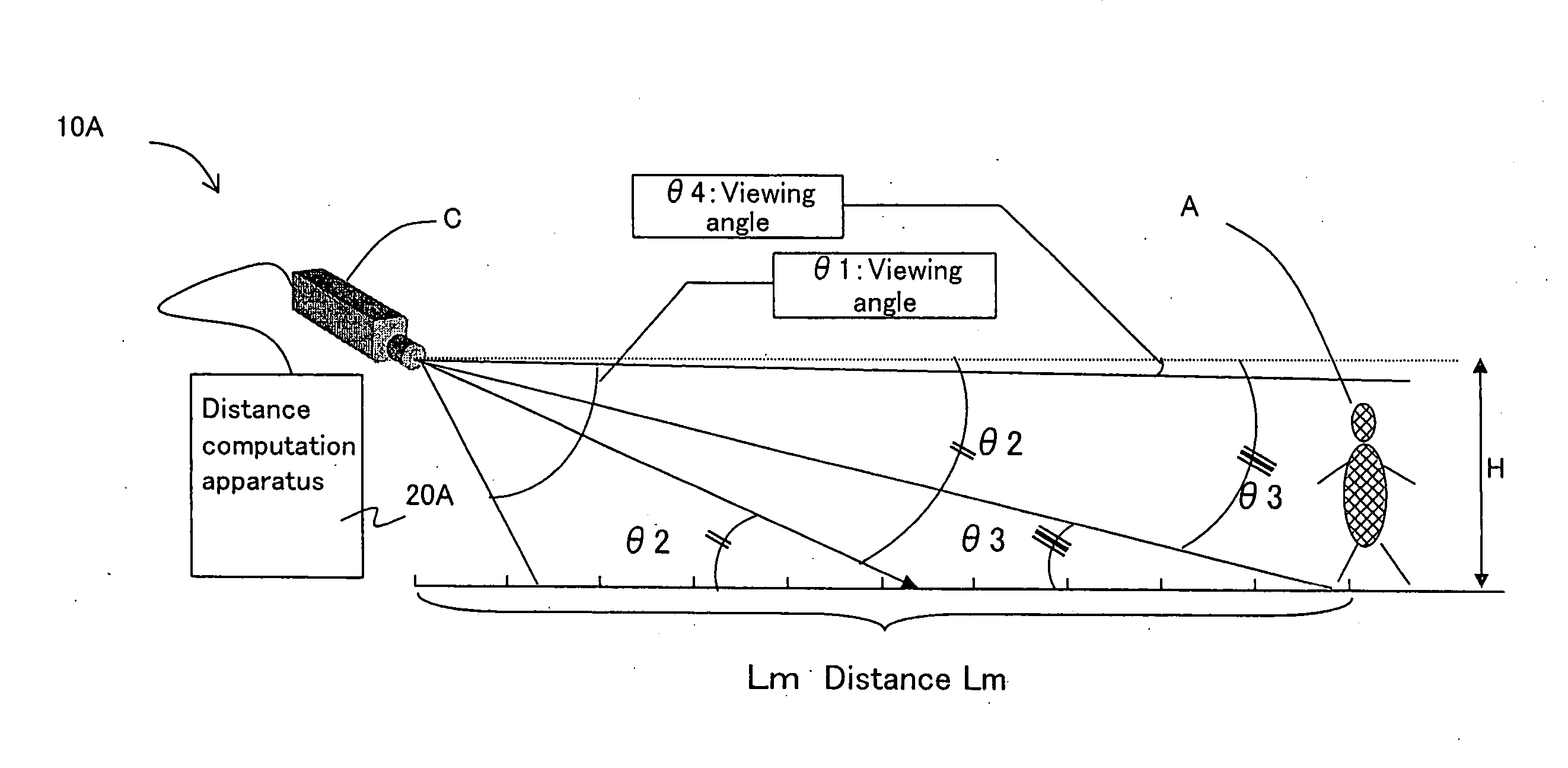
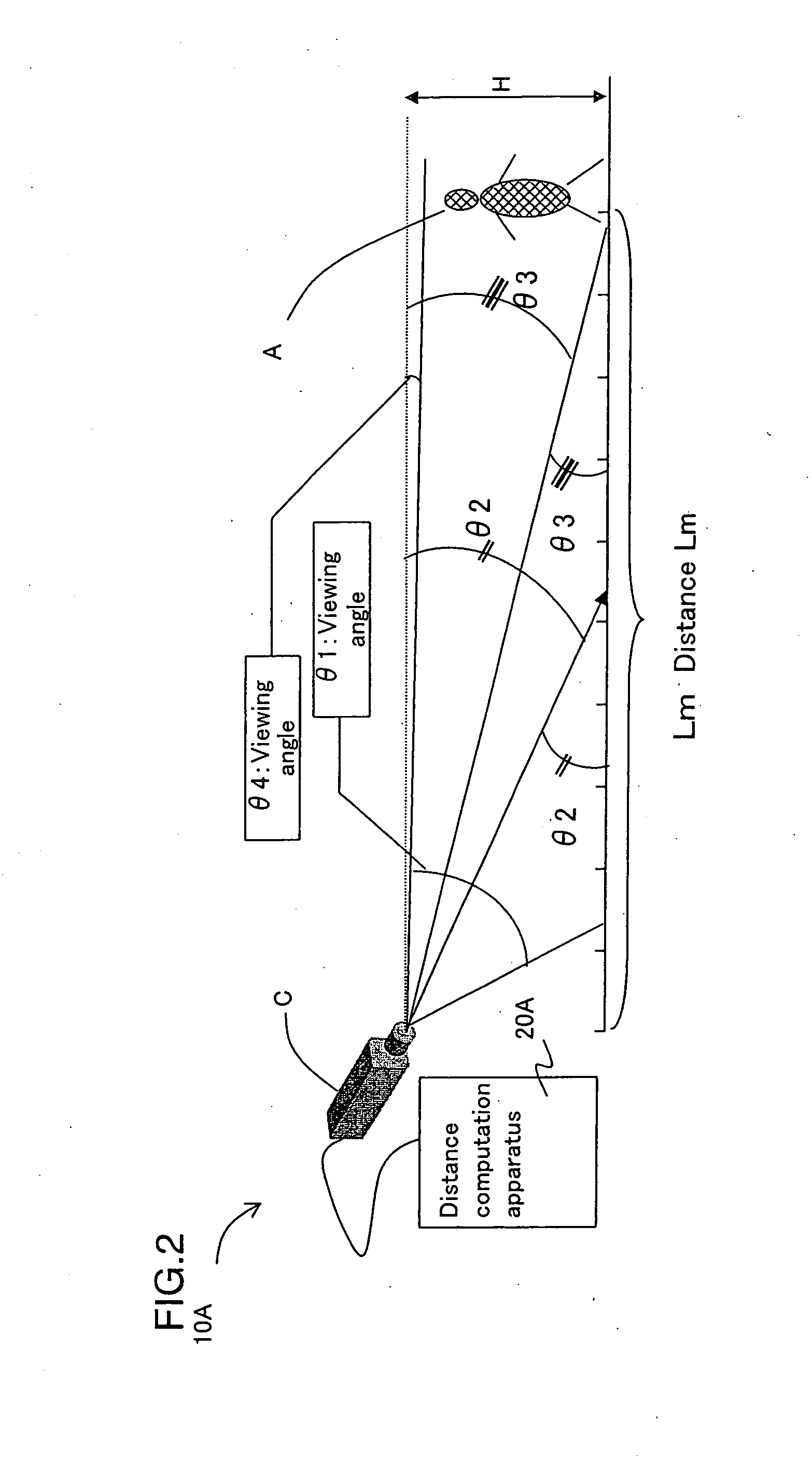
[0036] For example, the absolute value of difference which is this difference value is added for each line in the image information by a difference image summing apparatus. A total amount of pixel data for each line is output from the difference image summing apparatus. A maximum line No. Y1 among each and every one of the respective total amounts of pixel data for each of y number of lines in an image frame (y is the total number of lines in the image frame) is calculated by a first line computation section. The maximum line No. Y1 has a value greater than or equal to the object determination threshold. When it is assumed that the ground surface is flat and the object A to be imaged is on the ground, it is possible to calculate a distance data L, which indicates a distance between the object A to be imaged and the image capturing position by a distance calculation section based on the maximum line No. Y1 since it is considered that the maximum line No. Y1 is the coordinate at the foot of the object A to be imaged. Although the calculation of the distance data L is performed by a computation processing, it is possible to perform the processing more easily and rapidly by using a distance table memory in which the maximum line No. Y1 and the distance data L information are associated with each other.
[0037] By calculating a minimum line No. Y2, having a value greater than or equal to the object determination threshold using a second line computation section, among each and every one of the respective total amounts of pixel data for each of y number of lines in the image frame (y is the total number of lines in the image frame) from the difference image summing section, it is possible to calculate a height data h which indicates a height from the ground surface to the top of the object A to be imaged by a height data calculation section, based on the maximum line No. Y1 and the difference between the maximum line No. Y1 and the minimum line No. Y2 (maximum line No. Y1−the minimum line No. Y2). Although the calculation of the height data h is performed by a computation processing, it is possible to perform the processing more easily and rapidly by using a height table memory in which the maximum line No. Y1, the difference between the maximum line No. Y1 and the minimum line No. Y2 (maximum line No. Y1−the minimum line No. Y2) and the height data h information are associated with each other.
[0039] As described above, according to the present invention, it is possible to detect a distance between an object to be imaged and an image capturing position and the height from the ground surface to the top of the object A to be imaged by performing a simple image processing. As a result, the processing speed is improved. Furthermore, there is no need for two or more image capturing apparatuses as required by the conventional method or no need for matching the timing of capturing images between each image capturing apparatus. Thus, it is possible to prevent a decrease in computation accuracy. Furthermore, only one image capturing apparatus is required and there is no need for a computation unit to perform high speed processing. Thus, the cost of the apparatus can be reduced.

Problems solved by technology

(1) Due to the necessity of two or more image capturing apparatuses, there is a problem of increasing the cost of the distance measurement apparatus.
If the matching of timing between each image capturing apparatus is not sufficiently performed, there is a problem that the accuracy of computation decreases.
(3) A large amount of computation is required to calculate the coordinates corresponding to each other among a plurality of image information of images obtained by each image capturing apparatus.
Therefore, there is a problem that the processing speed is decreased or the cost required for a computation unit which performs with an improved processing speed is increased.

Method used


Image

  • Distance measurement apparatus, electronic device, distance measurement method, distance measurement control program and computer-readable recording medium
  • Distance measurement apparatus, electronic device, distance measurement method, distance measurement control program and computer-readable recording medium
  • Distance measurement apparatus, electronic device, distance measurement method, distance measurement control program and computer-readable recording medium

Examples


embodiment 1

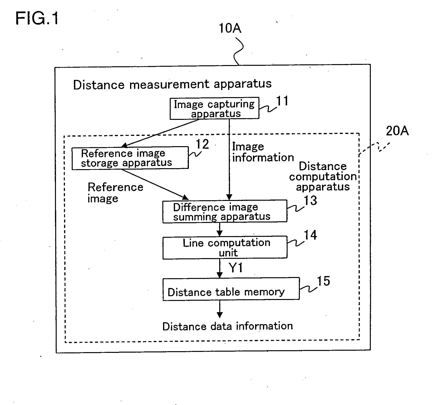
[0050]FIG. 1 is a block diagram showing a structure of a distance measurement apparatus according to Embodiment 1 of the present invention. Arrows shown in FIG. 1 indicate a flow pattern of data, and the processing involved.

[0051] In FIG. 1, a distance measurement apparatus 10A includes an image capturing apparatus 11 which functions as an image capturing section, a reference image storage apparatus 12 which functions as a reference image storage section, a difference image summing apparatus 13 which functions as a difference image summing section, a first line computation unit 14 which functions as a first line computation section and a distance table memory 15 which functions as a distance data obtaining section. A distance computation apparatus 20A is configured by the reference image storage section 12, the difference image summing apparatus 13, the first line computation unit 14 and the distance table memory 15. Referring to the distance computation apparatus 20A, a distance d...

embodiment 2

[0085]FIG. 5 is a block diagram showing a structure of a distance measurement apparatus according to Embodiment 2 of the present invention. In FIG. 5, the constituents which have the same working effect as ones shown in FIG. 1 are denoted by the same reference numerals, and description thereof will be omitted.

[0086] In FIG. 5, a distance measurement apparatus 10B according to Embodiment 2 includes an image capturing apparatus 11 which functions as an image capturing section, a reference image storage apparatus 12 which functions as a reference image storage section, a difference image summing apparatus 13 which functions as a difference image summing section, a first line computation unit 14 which functions as a first line computation section, a distance table memory 15 which functions as a distance data obtaining section, a second line computation unit 16 which functions as a second line computation section, and a height table memory 17 which functions as a height data obtaining s...

embodiment 3

[0095] The distance data computation sections in Embodiments 1 and 2 can be configured by hardware or software. In Embodiment 3, a case in which the distance data computation section in Embodiment 2 is configured by software will be described.

[0096]FIG. 7 shows a block diagram showing a structure of a distance measurement apparatus according to Embodiment 3 of the present invention.

[0097] In FIG. 7, other than the image capturing apparatus 11 and the reference image storage apparatus 12, the distance measurement apparatus 10C according to Embodiment 3 includes a distance data computation section 30, an operation input section 31 capable of issuing a variety of input instructions (e.g., activating or stopping the processing of distance measurement) and a display section 32 capable of displaying the display contents on a display screen in accordance with the variety of input instructions. The distance data computation section 30 includes a CPU 33 (central processing unit) as a contr...


PUM


Abstract

A distance measurement apparatus includes comprising: an image capturing section for capturing an image of an object to be imaged, for which information is known regarding an image capturing position, an angle of image capturing direction and an image capturing area; a reference image storage section for receiving the image from the image capturing section and storing an image information of the image as a reference image; and a distance data computation section for determining a distance data L, the distance data L indicating a distance between the object to be imaged and the image capturing position, the determination being based on a lowermost position information of the object to be imaged in an image frame, the lowermost position information being based on a difference value between the image information of the reference image stored in the reference image storage section and an image information of an image newly captured by the image capturing section.

Description

[0001] This Nonprovisional application claims priority under 35 U.S.C. §119(a) on Patent Applications No. 2005-84940 filed in Japan on Mar. 23, 2005, the entire contents of which are hereby incorporated by reference. BACKGROUND OF THE INVENTION [0002] 1. Field of the Invention [0003] The present invention relates to: a distance measurement apparatus capable of determining a distance from the apparatus to an object to be imaged and a size of the object to be imaged (the height from ground surface). The distance and size are determined based on an image. The size of the image varies depending on the distance to be imaged from the apparatus. The present invention also relates to; an electronic device (e.g. a vacuum clear running randomly in a room or a surveillance camera) having the distance measurement apparatus mounted thereon; a distance measurement method using the distance measurement apparatus; a distance measurement control program for causing a computer to execute each step of...

Claims


Application Information

Patent Timeline
IPC IPC(8): G06K9/00
CPCG01B11/024G01C3/04
Inventor NAKAJIMA, TATSUSHINAGASAWA, SHUNSUKE
Owner SHARP KK
Learn More