Linear motion guide unit

a technology of motion guide and guide unit, which is applied in the direction of linear bearings, shafts and bearings, bearings, etc., can solve the problems of difficult selection and use of lubricant applicators, difficulty in replenishing lubricant quantity, and still remains a further challenge. , to achieve the effect of reducing maintenance costs, reducing maintenance costs, and increasing the amount of lubrican

Active Publication Date: 2006-09-28
NIPPON THOMPSON
View PDF4 Cites 40 Cited by
  • Summary
  • Abstract
  • Description
  • Claims
  • Application Information

AI Technical Summary

Benefits of technology

[0013] In view of the above shortcomings related with the prior linear motion guide unit in which a slider is made therein with only a return passage composed of a tubular member of cellular structure impregnated with lubricant, the present invention derived from many repeated empirical results has as its principal object the provision of a linear motion guide unit in which a slider is made therein with a lubricant reservoir to apply lubricant for long-lasting period of time, and a leading member to constantly supply the lubricant from the lubricant reservoir to a tubular member inside a return passage. Moreover, the present invention provides a linear motion guide unit in which the lubricant reservoir is made replaceable to make it easier to handle it, and also made compact in construction as well as inexpensive in production cost to achieve steady maintenance-free operation.
[0022] With the linear motion guide unit constructed as stated earlier, the return passage made in the slider is constituted with the tubular member made to have the cellular structure adapted to be impregnated with lubricant. The lubricant reservoir installed in the slider is to increase the amount of lubricant supplied to the tubular member. The leading member inside the slider makes sure of applying or leading gently the lubricant from the lubricant reservoir towards the tubular member without causing any seepage or leakage. Moreover, the lubricant reservoir is made replaceable with new one and easier to handle it with less care. The lubricant reservoir and the leading member made simple in construction are also contribute to the provision of the slider that is less in production cost, compact in construction, and easier to shrink it in construction. The linear motion guide unit with the constructional features as stated earlier is allowed to work over an extended range more than three times in maintenance-free operation as compared with the conventional one having just the lubricant-impregnated tubular member.
[0023] The linear motion guide unit constructed according to the present invention makes it possible to provide the slider which can harbor ample quantity of lubricant enough to make certain of reduced maintenance for lubrication. The linear motion guide unit of the present invention can work over an extended range, for example more than three times in maintenance-free operation as compared with the conventional one having just the lubricant-impregnated tubular member.
[0024] With the linear motion guide unit of the present invention, moreover, the lubricant reservoir has the cartridge or shell of cellular structure to allow the leading member to bring out the lubricant from anywhere around the cartridge. This means that the leading member is permitted to have a simple, for example a circular contour, and also make connection with the lubricant reservoir anywhere with no adverse influence on stiffness or mechanical strength of the slider. Thus, the cartridge of cellular structure is also contribute to the provision of the slider that is high in functional effect, even with less in production cost and compact in construction. Further, the cartridge of the lubricant reservoir, since made exchangeable for another one, is easier in handling. The lubricant reservoir and the leading member are all made simple in construction. The lubricant reservoir holds therein the occluding member that is able to accumulate ample lubricant without causing any leakage or seepage. The leading member serves to take the lubricant oozing out of the cartridge and transfer gently the lubricant to the tubular member with no leakage or loss to lubricate the rolling elements.

Problems solved by technology

However, it still remains a further challenge to the prior linear motion guide unit as recited earlier to continue supplying any additional lubricant to the rolling elements.
With the linear guideway with self-lubrication system reserving only as much lubricant as once needed, nevertheless, the reserved quantity of lubricant might be not necessarily enough to ensure the maintenance-free operation, while how quantity of lubricant is replenished gets unknown easily.
Moreover, the lubricant applicators are much tough to select and use them.
The prior linear guideway with the lubricating structure as stated earlier is highly tough to work it because a groove to fit over the diversion device has to be cut in the slider.
The linear motion guide unit of the type recited in the last-mentioned prior art, moreover, would be unsuitable for steady application of lubricant to every location to be lubricated because the lubricant is left to flow in gravitational direction.

Method used


Image

  • Linear motion guide unit
  • Linear motion guide unit
  • Linear motion guide unit

Examples


Embodiment Construction

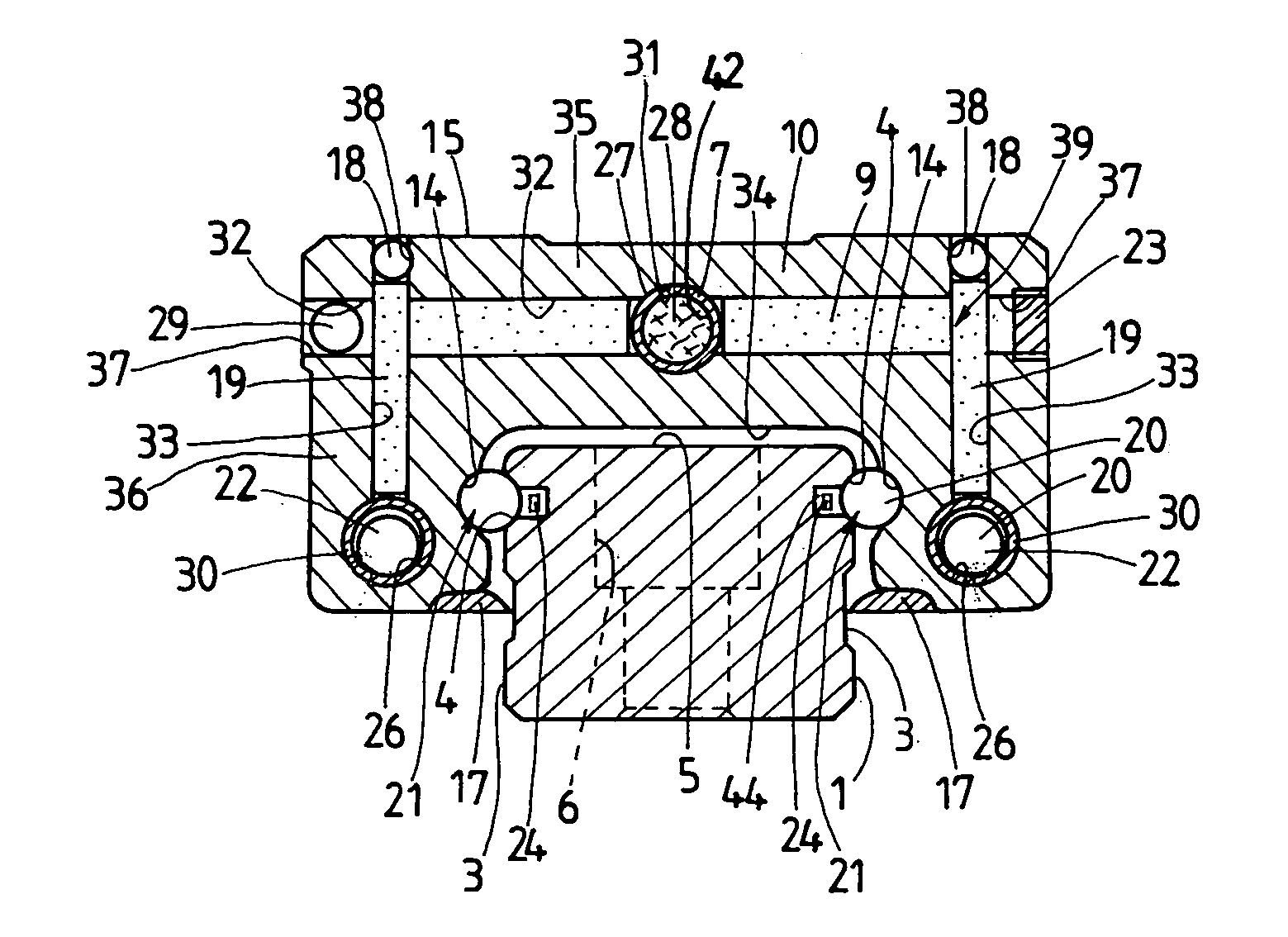
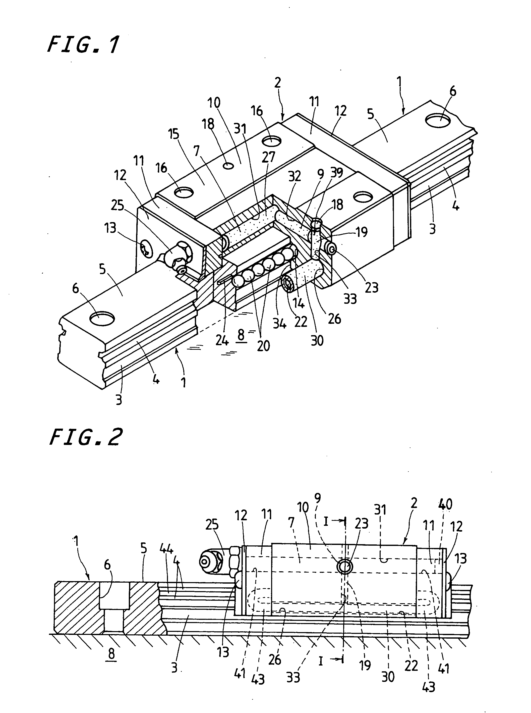
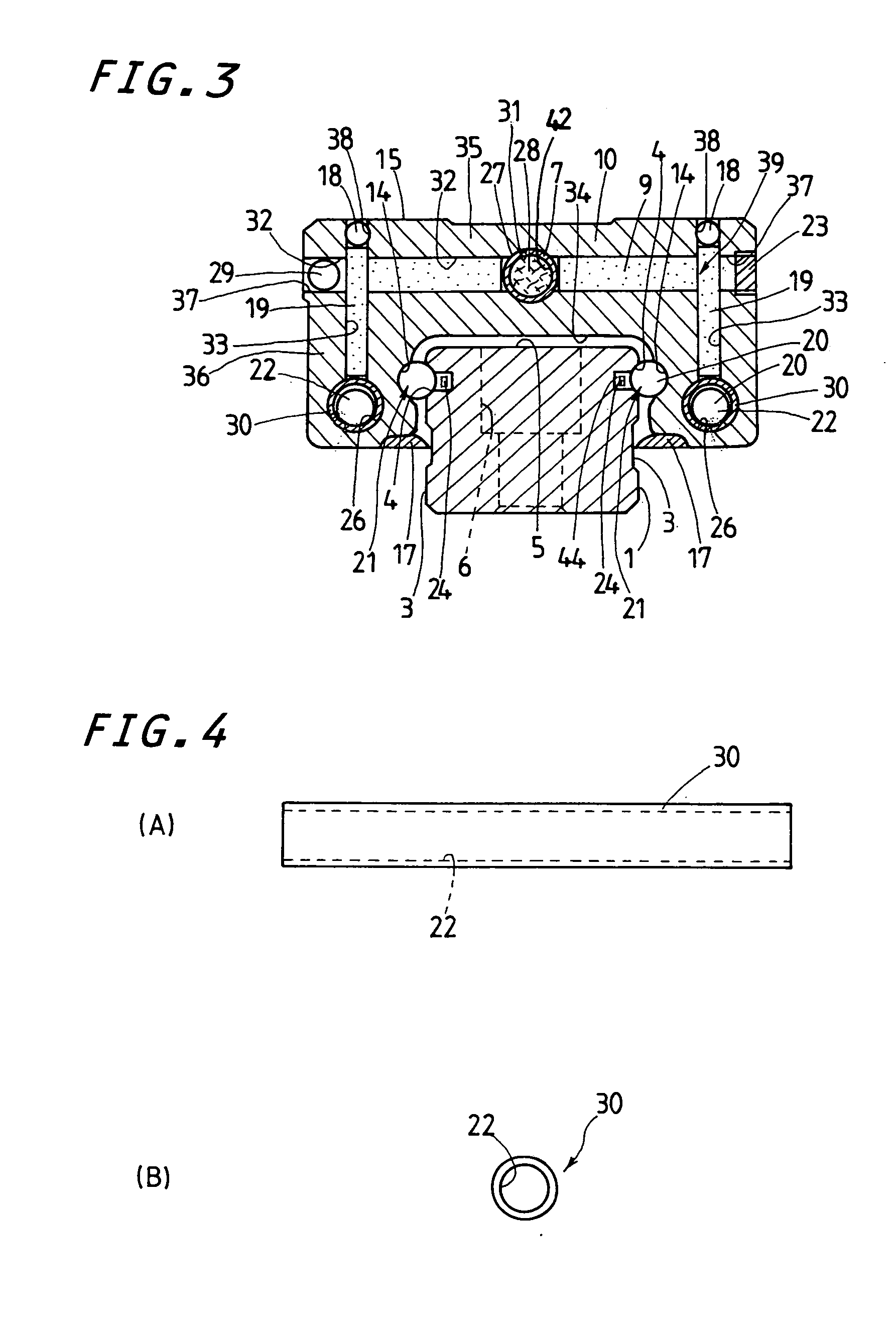
[0034] The linear motion guide unit according to the present invention is well adapted for use in any relatively sliding components in machinery as diverse as semiconductor fabricating equipment, assembly machines, inspection instruments, medical instruments, measurement / inspection instruments, and so on. The linear motion guide unit of the present invention is expected to get any parts moving in a reciprocating manner with precise position control and smooth movement, despite being made much less in construction, and further ensure positive maintenance-free operation regarding lubrication for rolling elements even when used in the various machines as recited above under high-speed, high-cyclic operating condition.

[0035] A preferred embodiment of a linear motion guide unit according to the present invention will be explained hereinafter in detail with reference to the accompanying drawings. The linear motion guide unit of the present invention may be equally adapted for any type of...


PUM


Abstract

A linear motion guide unit with a lubricating system made compact or slim in construction with inexpensive production cost and permitted to lubricatesliding contacts with accompanying reduced maintenance. The slider has a tubular member for a return passage to allow rolling elements rolling through there, a lubricant reservoir to accumulate lubricant, and a leading member to transfer the lubricant from the reservoir to the tubular member. The lubricant is supplied from the reservoir into the return passage via the leading member. The lubricant reservoir including an occluding member packed in a cartridge to keep the lubricant inside the cartridge.

Description

FIELD OF THE INVENTION [0001] The present invention relates to a linear motion guide unit comprised of an elongated guide rail, and a slider that is allowed to move on the elongated guide rail relatively to the guide rail by virtue of more than one rolling element. BACKGROUND OF THE INVENTION [0002] The recently remarkable development in extensively various machines including semiconductor fabricating equipment and so on has needed linear motion guide units that are expected to get any parts moving in a reciprocating manner with precise position control and smooth movement, despite being made reduced in construction. Meanwhile, modern linear motion guide units have been especially required to meet with the maintenance-free operation regarding lubrication for rolling elements from many aspects of conserving energy as well as keeping running cost and maintenance cost of equipment reasonable. A diversity of machines including semiconductor fabricating equipment, assembly machines, insp...

Claims


Application Information

Patent Timeline
Patent Type & Authority Applications(United States)
IPC IPC(8): F16C29/06F16C33/10
CPCF16C29/0611F16C29/064F16C33/6614F16C33/6648
Inventor AGARI, NORIMASAISHIHARA, TOYOHISAFURUTA, KAZUE
Owner NIPPON THOMPSON
Why Eureka
Try Eureka