Thermal infrared camera tracking system utilizing receive signal strength

a technology of thermal infrared camera and receive signal strength, which is applied in the field of tracking and location, can solve the problems of structural damage, structure or building creating a dangerous environment with limited or no visibility, and not being able to exit the burning structure without assistance, so as to reduce the risk of injury and less time

Inactive Publication Date: 2006-09-28
GODEHN KATAREYA
View PDF3 Cites 68 Cited by
  • Summary
  • Abstract
  • Description
  • Claims
  • Application Information

AI Technical Summary

Benefits of technology

[0012] The present invention provides the user with visual indicators viewable on the video display of the thermal infrared camera to track and locate a firefighter wearing or carrying a portable unit. The visual indicators are viewed on the video display as a unique identification (ID) name and a receive signal strength indication (RSSI) value derived from RF signal transmitted by a portable unit. Furthermore, the present invention is capable of displaying more than one identification (ID) name(s) on the video display of a thermal infrared camera. A user of the present invention can select one specific portable unit to track which is identifiable by its unique identification (ID) name displayed on the video display of the thermal infrared camera. A user by selecting a identification (ID) name initializes displaying of the RSSI value as visual indicators corresponding directly to the identification (ID) name selected. The user by pointing the thermal infrared camera in different directions within the structure and observing the RSSI visual indicators for a maximum peak RSSI value, the user is capable of determining an approximate direction to a portable unit and an approximate distance to a transmitting portable unit. The visual indicators indicating the strength of the wireless RF signal and the identification (ID) name are simultaneously displayed on the video display with the thermal infrared video image. Furthermore, a rescue team using the present invention within a hazardous environment searching for a co-worker, would under most circumstances be required to spend less time within the hazardous environment, thus reducing the risk of injury to rescue team members.

Problems solved by technology

However, there still exists a need in the art for additional features to improve a thermal infrared camera as a more effective search tool in used for locating a firefighter that has become trapped and or injured and is not capable of exiting the burning structure without assistance.
A burning structure or building creates a dangerous environment having limited or no visibility due to smoke, and structural damage which occurs when a structure or building burns.
The structural integrity of a burning building diminishes, creating a dangerous environment in the form of, e.g., falling debris from walls and or ceilings or possible total structural failure resulting in a collapse of the structure.
For example, if a firefighter has been covered by fallen debris within a burning building, in this situation a thermal infrared camera used as a search tool to locate a firefighter is not normally capable of penetrating the debris covering the firefighter causing a situation where the firefighting rescue team may not be able locate the firefighter.
A burning building or structure limits visibility and creates a hazardous environment with a lethally toxic atmosphere.
On occasion a firefighter wearing a SCBA may become trapped, lost, entangled, injured and or cover by debris within a burning structure making exiting the structure difficult or impossible before the firefighter's SCBA fresh air supply is exhausted.
If a burning structure is relatively large and or the location of the firefighter within the structure in not known, the rescue team may spend an excessive amount of time searching the entire structure, room by room and or floor by floor in an effort to visibly locate a co-worker using a thermal infrared camera.
This method of relying solely on a visual search method using a thermal infrared camera system is very time consuming and requires the rescue team to conduct an extensive search of the interior of the burning structure to locate the co-worker.
Since, the SCBA worn by firefighters has a limited amount of fresh air within the air cylinder, and the fire can spread very rapidly, the time to locate and extract the firefighter from the burning structure is critical.
Furthermore, a firefighter not wearing an SCBA may become trapped, injured and or covered by debris within the burning structure, a firefighter in this situation would certainly need to be almost immediately located and extracted from the structure.
The protective equipment worn by a firefighter is designed to protect the firefighter from high temperatures, however the protective equipment can become relatively close to the surrounding environment temperature causing a situation that would render a firefighter virtually undetectable by a thermal infrared camera.
A GPS satellite signals necessary to for a GPS receiver to operate normally will not penetrate a building or is not accurate within a building or structure.
This method offers little assist to a firefighting rescue team which must operate and navigate within the interior of the burning structure.
A firefighting rescue team performing a search and rescue operation to locate a firefighter within the structure at a fire scene, upon entering a burning structure would normally not be familiar with the interior and or general floor plan of the structure, falling debris from the deteriorating structure and the dense smoke created by the fire further hinders rescue operations and locating of a firefighting co-worker.

Method used


Image

  • Thermal infrared camera tracking system utilizing receive signal strength
  • Thermal infrared camera tracking system utilizing receive signal strength
  • Thermal infrared camera tracking system utilizing receive signal strength

Examples


Embodiment Construction

[0021] Referring to the drawing, fields of applicability of the present invention will become evident from the detailed description and examples provided within the preferred embodiment(s). It should be noted that while indicative of the preferred embodiment(s), the description and examples are intended for the purposes of illustration only and are not intended to limit the scope of the present invention.

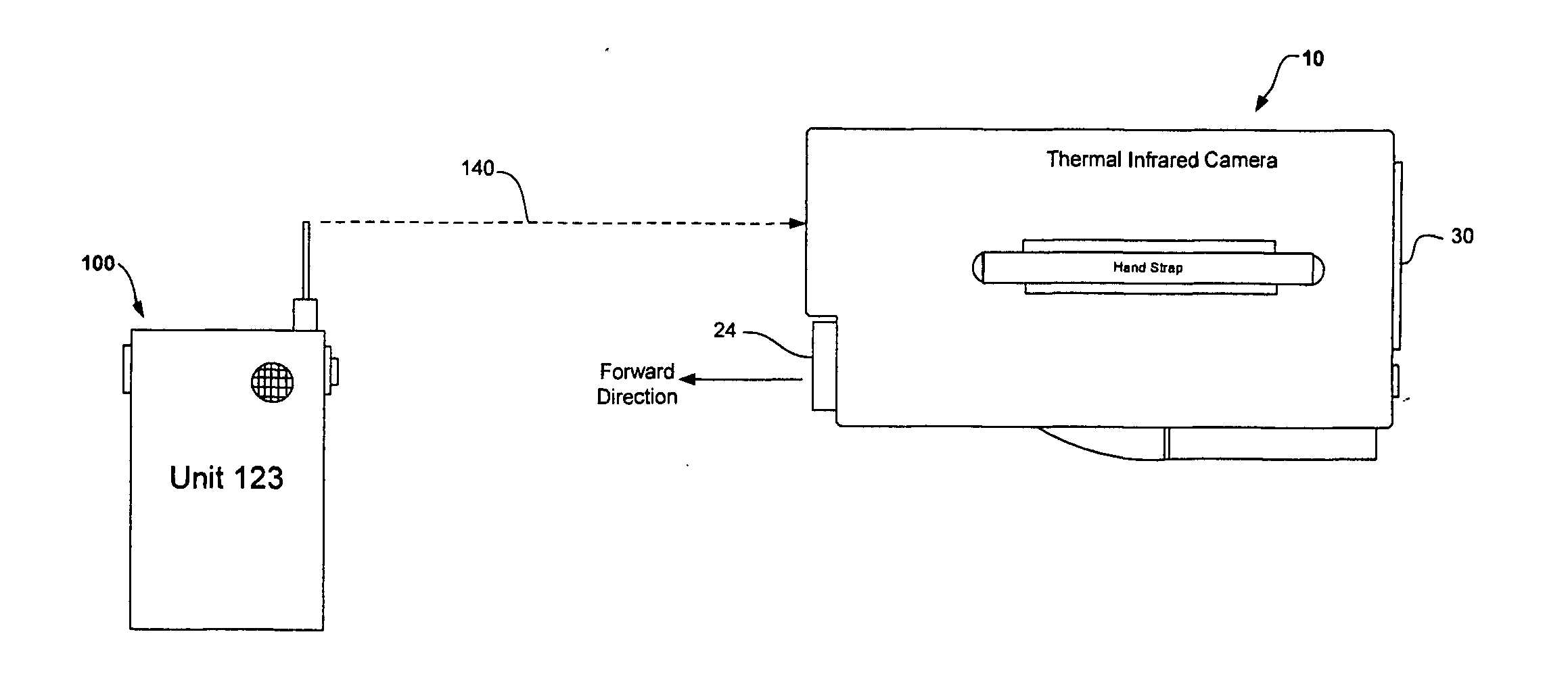
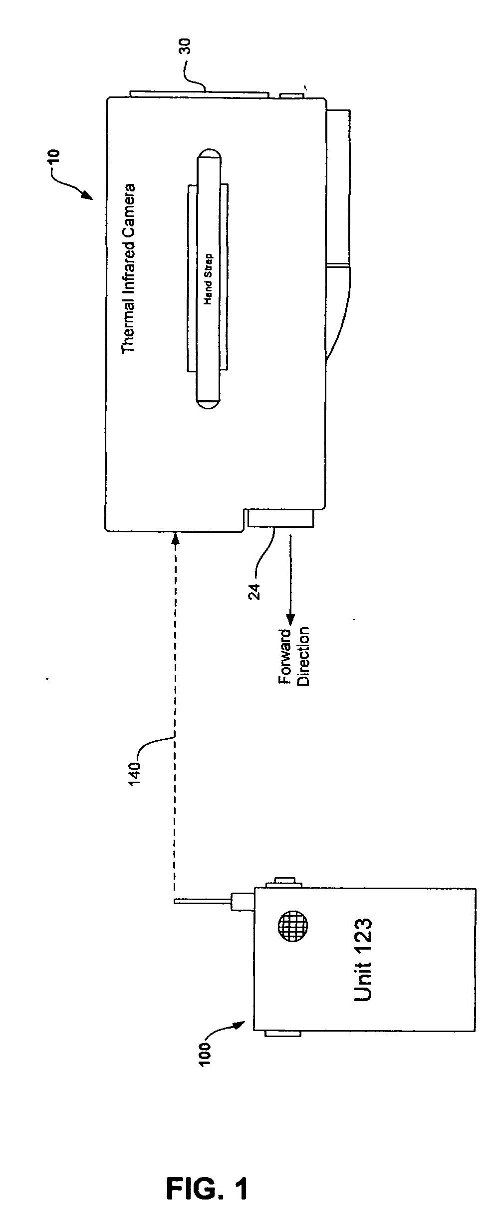
[0022] Now referring to FIG.1 is a perspective view of a thermal infrared camera tracking system utilizing receive signal strength with the preferred embodiment of the present invention. FIG. 1 illustrates a wireless RF signal 140 transmitted by a portable unit 100 being received at the thermal infrared camera 10. The thermal infrared camera 10 is equipped to receive, process and display information pertaining to a wireless RF signal 140 transmitted by the portable unit 100 which can be worn, carried or attached to an SCBA of a firefighter or first responder.

[0023] The wireless RF...


PUM


Abstract

A thermal infrared camera tracking system utilizing receive signal strength is provided for firefighters and emergency service first responders, the system can include a plurality of portable units which can be individually tracked and located using information simultaneously displayed with the thermal infrared video image on the video display of the thermal infrared camera. The thermal infrared camera encompasses a RF transceiver for receiving wireless RF signals transmitted by one or more portable unit(s). The RF signal transmission of a portable unit is displayed as a unique identification (ID) name and when displayed on the video display is an indication an emergency condition. The user of the thermal infrared camera selects one identification (ID) name (if more than one identification (ID) name is displayed) and views visual indicators on the video display being indicators of the strength of the RF signal transmitted by the portable unit to track and locate the selected portable unit. The user of the thermal infrared camera upon selecting a identification (ID) name, views the visual indicators indicating a RSSI value to determine a direction to and distance from the selected portable unit.

Description

CROSS-REFERENCE TO RELATED U.S. APPLICATION [0001] This application claims benefits, and claims priority to, U.S. Provisional Patent Application Ser. No. 60 / 664,281, filed on Mar. 22, 2005 by Katareya Godehn entitled “Thermal Infrared Camera with location and tracking utilizing receive signal strength”.BACKGROUND OF THE INVENTION [0002] 1. Field of the invention [0003] The present invention generally relates tracking and location, and more particularly to enhancements for thermal infrared cameras, whereby a thermal infrared camera is capable of producing and displaying information as visual indicators used to track and locate a transmitting portable unit worn or carried by a user. The thermal infrared camera derives information from the RF signal transmitted by a portable unit, and displays the information as visual indicators on the video display which is used to track and locate the portable unit. The thermal infrared video image is displayed on the video display simultaneously wi...

Claims


Application Information

Patent Timeline
Patent Type & Authority Applications(United States)
IPC IPC(8): G03B17/00
CPCG01S3/046G01S3/38G01S13/825G01S13/886G08B21/0211G08B21/0247G08B21/0294H04N5/33G01S13/867
Inventor GODEHN, KATAREYA
Owner GODEHN KATAREYA
Why Eureka
Try Eureka