Controller for injection molding machine

a technology of controller and injection molding machine, which is applied in the direction of electric programme control, program control, instruments, etc., can solve the problems of delay in the changeover to the holding pressure control, injection velocity changeover, etc., and achieve stable pressure control, more accurate and stable changeover, suppress the effect of peak pressure dispersion

Active Publication Date: 2006-09-28
FANUC LTD
View PDF4 Cites 9 Cited by
  • Summary
  • Abstract
  • Description
  • Claims
  • Application Information

AI Technical Summary

Benefits of technology

[0020] A screw motion error (motion deficiency, too much motion) caused by time lag between the point when the changeover conditions of the injection velocity and the changeover conditions from the injection velocity control to the pressure control are actually satisfied and the point when it is detected that the changeover conditions are satisfied is compensated. This enables more accurate and stable changeover. Especially at the time of changeover from the injection velocity control to the pressure control, it is possible to hold down the generated peak pressure and suppress the dispersion of the peak pressure, which makes it possible to carry out stable pressure control.

Problems solved by technology

In result, the injection velocity changeover and the changeover to the holding pressure control are delayed.

Method used


Image

  • Controller for injection molding machine
  • Controller for injection molding machine
  • Controller for injection molding machine

Examples


Embodiment Construction

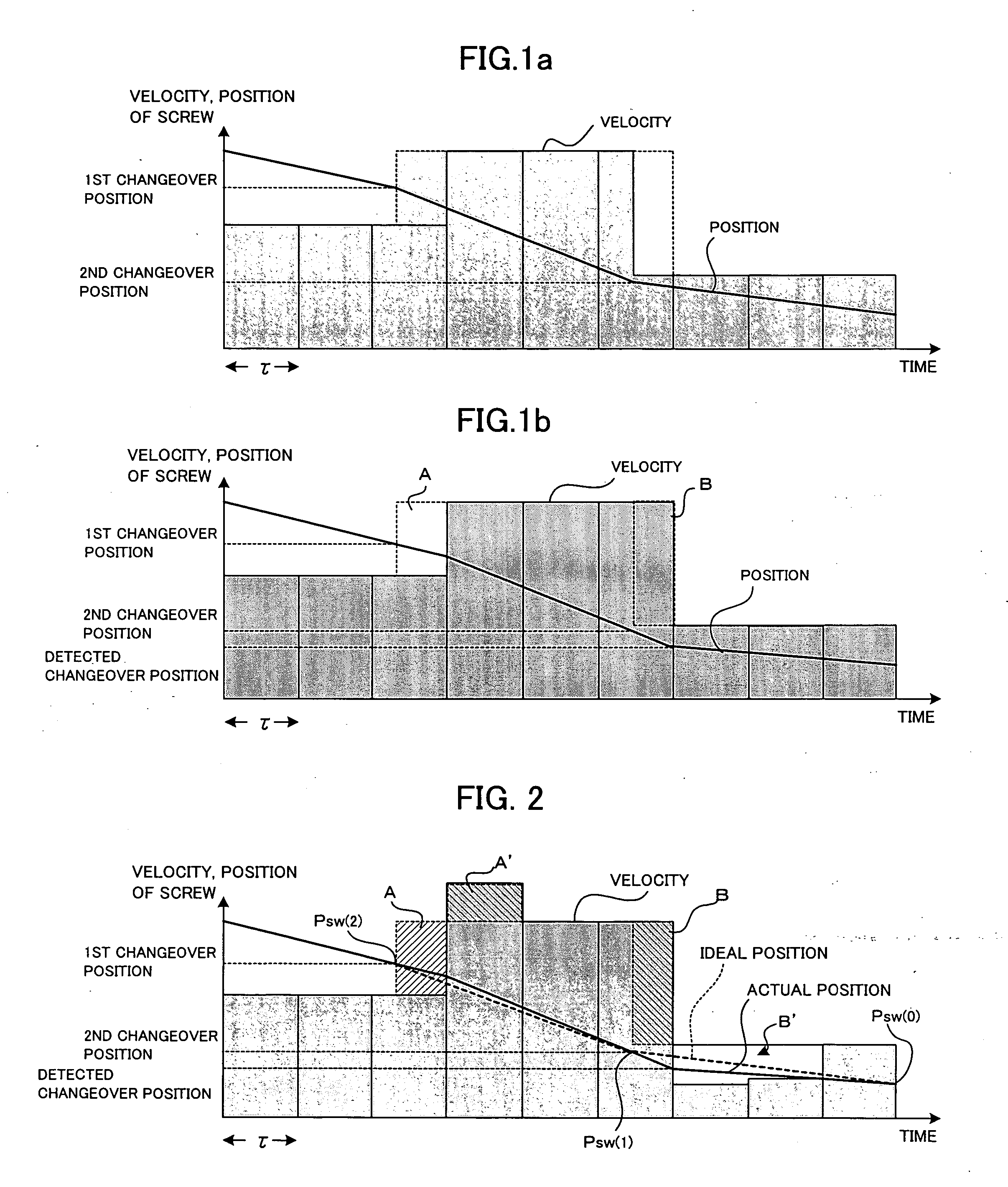
[0028]FIGS. 1a and 1b are explanatory views of an injection velocity changeover in an injection process. In FIGS. 1a and 1b, a horizontal axis denotes time, and a vertical axis denotes injection velocity and a screw position. The injection velocity is expressed as a motion amount (motion command) per unit of time, namely (velocity×τ=motion amount), where a motion amount for the duration of a sampling period (position / velocity loop processing period) τ is area per unit of time τ, and height thereof is velocity. The injection velocity (motion amount in a sampling period) is shown by a bar graph, and the screw position by a line graph.

[0029]FIG. 1a shows an ideal state in which a velocity command is switched, and an injection velocity is switched at a set velocity changeover position.

[0030]FIG. 1b shows a state of a conventional velocity changeover. In case that a position and velocity of a screw are controlled by means of a processor, based on the motion command, a detection positio...


PUM

PropertyMeasurementUnit
velocityaaaaaaaaaa
injection velocityaaaaaaaaaa
timeaaaaaaaaaa

Abstract

A controller of an injection molding machine which compensates a delay in an injection velocity changeover and a delay at the time of changeover to the pressure-holding process, and is capable of more accurate and stable injection velocity control and changing control from the injection velocity control to pressure control. In the injection process, a motion command is outputted in every sampling period τ according to the command injection velocity. When a screw position overshoots the set velocity changeover positions Psw(2) and Psw(1), a motion command based on a velocity command of the next interval is outputted from the next period. However, there is time lag between the point when the set changeover position is reached and the point when the motion command is changed after detection thereof. There generates a motion deficiency in a motion amount shown by mark A and overshoot shown by B. Motion commands of the next period or the next and subsequent several periods are compensated with errors in the motion amount caused by the time lag used as compensation amounts A′ and B′. The generated error motion amount is immediately compensated, which enables accurate velocity changing control. By performing the compensation in the same manner when the injection velocity control is switched to the holding pressure control, it is possible to suppress the peak pressure and the dispersion.

Description

BACKGROUND OF THE INVENTION [0001] 1. Field of the Invention [0002] The present invention relates to a controller for an injection molding machine, and more specifically to changeover of an injection velocity in an injection process and changeover from an injection-velocity control in the injection process to a resin-pressure control in a pressure-holding process. [0003] 2. Description of Related Art [0004] With regard to an injection process in the molding operation of an injection molding machine, the method of controlling the injection process by changing injection velocity (forward velocity of a screw) according to the position of the screw that advances in the axial direction to inject resin into the mold or according to injection pressure (resin pressure) during injection and moreover according to the elapsed time from the start of injection is widely employed. As to changeover from the injection process (injection velocity control) to the pressure-holding process (pressure co...

Claims


Application Information

Patent Timeline
Patent Type & Authority Applications(United States)
IPC IPC(8): B29C47/92B29C48/92
CPCG05B19/404G05B19/416B29C47/92G05B2219/45244G05B2219/42094
Inventor UCHIYAMA, TATSUHIROMARUYAMA, JUNPEI
Owner FANUC LTD
Why Eureka
Try Eureka