
Pull-out access cooler unit

a cooler unit and pull-out technology, applied in the field of compact refrigeration units, can solve the problems of difficulty in removing or detecting items, difficulty in facilitating access to stored items, and difficulty in detecting items at times for consumers, so as to facilitate access and increase the user-friendliness of the uni

Active Publication Date: 2006-10-05
U LINE CORP A WI CORP
View PDF8 Cites 83 Cited by
  • Summary
  • Abstract
  • Description
  • Claims
  • Application Information

AI Technical Summary

Benefits of technology

[0013] The present invention is a compact refrigeration unit for the cold storage of food and beverages, particularly bottled wine. The unit has one or more pull-out assemblies each with a door panel and a storage area for supporting the cooled items, e.g. wine bottles, and allowing them to be pulled out from the interior of the cabinet for easy access. Other features, such as a glass door front and cascading wine racks, can be also be provided to facilitate access and increase the user-friendliness of the unit.
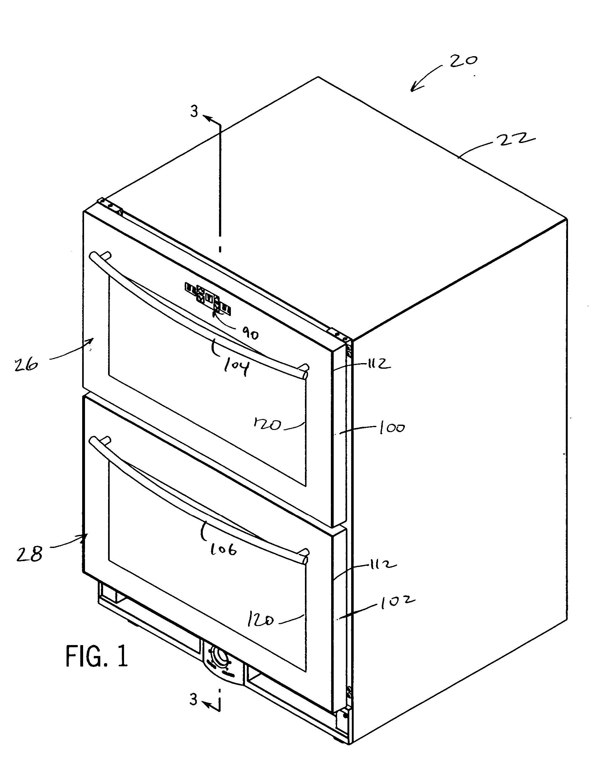
[0017] The refrigeration system can be controlled by a user control which is accessible from an outside of the cabinet for setting and adjusting the temperature zones. Preferably, the user control is one or more capacitive switches which are set behind a glass face panel of one of the door panels. The face panel can be part of a two-pane thermopane. The switch can be disposed inside of the thermopane or outside of the thermopane but behind an extending portion of the face panel. Either way, the capacitance switch allows for controlling the temperature inside the cabinet without opening either pull-out assembly (and thereby losing cooling). Also, the glass panel allows the inside of the cabinet to be visually inspected without opening either of the pull-out assemblies, and it also protects the switch from splashing (as when cleaning) or mechanical contact.
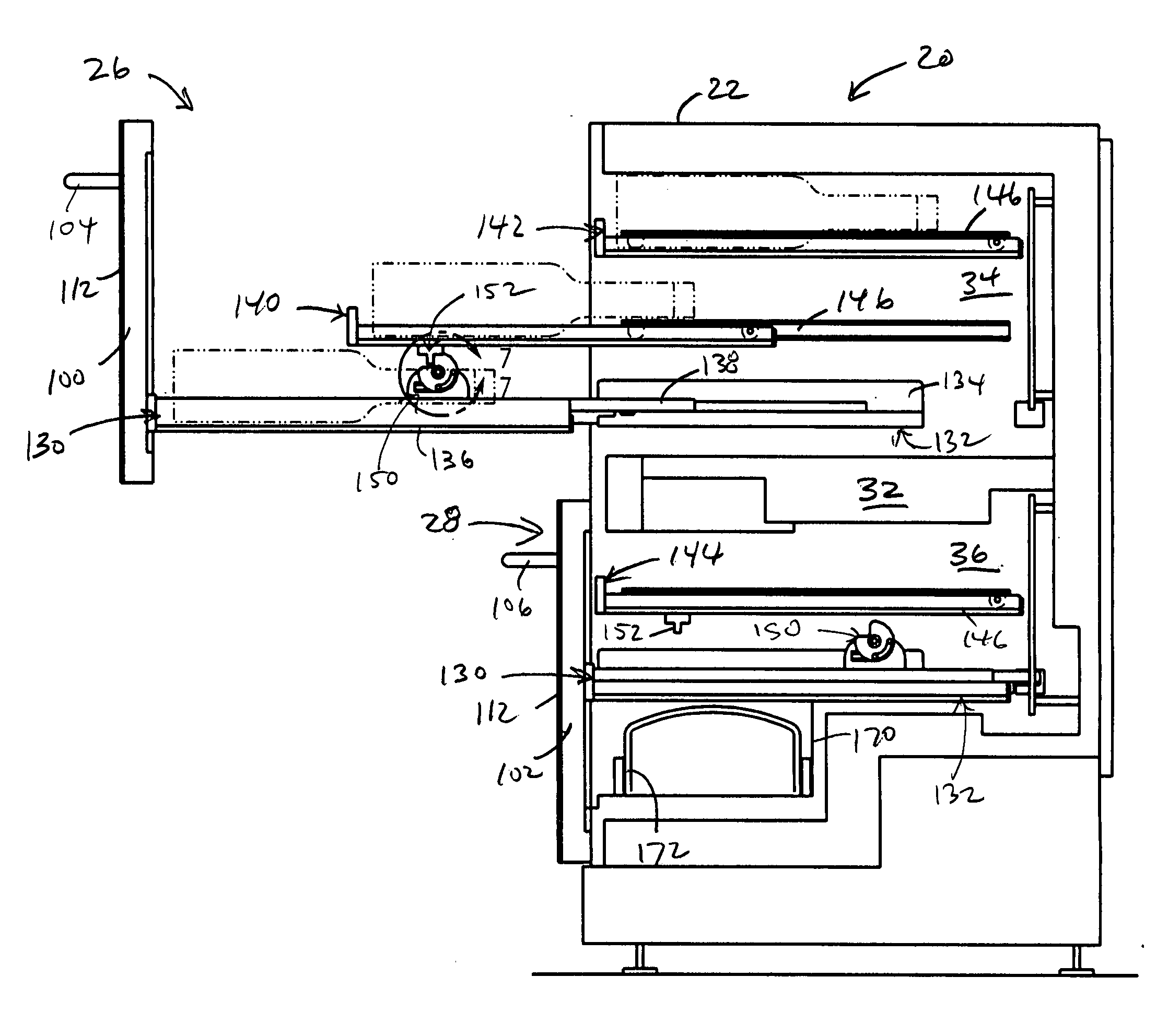
[0018] In another preferred form, one or more of the pull-out assemblies can have multiple vertically-spaced racks. At least one of the two racks in each pull-out assembly can be made to extend from the cabinet different distances simply by pulling the door panel away from the cabinet. In other words, these racks are mounted to move with the door panel and slide-out from the cabinet in a cascading fashion such that the lowest rack extends out from the cabinet farther than the rack vertically above it, which would extend out farther than the rack above it if there were three cascading racks, for example. This facilitates unobstructed access to each rack, especially the lower rack(s). The pull-out assembly can have two, three or more racks, of the same or differing sizes.
[0021] The cam is releasably held in each of the first and second positions by one or more detent arrangements, which preferably include a single spring tab with a projection parallel to the axis of rotation of the cam that is received in one of two pockets in the cam located to correspond to the first and second positions of the cam. The detent arrangement holds the cam in either position until the follower rack is fully extended or retracted, in which case the follower rack stops sliding and the force of engagement between the cam and catch members overcomes the force of the detent. The cam mechanism can be deactivated, that is, rendered inoperable from engaging the catch member sufficient to move the follower rack, by sufficiently increasing the rate at which the drive rack is extended or retracted.

Problems solved by technology

For example, accessibility to the stored items remains an issue of concern.
Thus, it can be difficult at times for the consumer to remove an item or to detect which items are stored where in the cabinet.
However, even these units have accessibility issues because generally each rack must be pulled out from the cabinet in order to see all of the bottles on a rack.

Method used


Image

  • Pull-out access cooler unit
  • Pull-out access cooler unit
  • Pull-out access cooler unit

Examples


Embodiment Construction

)

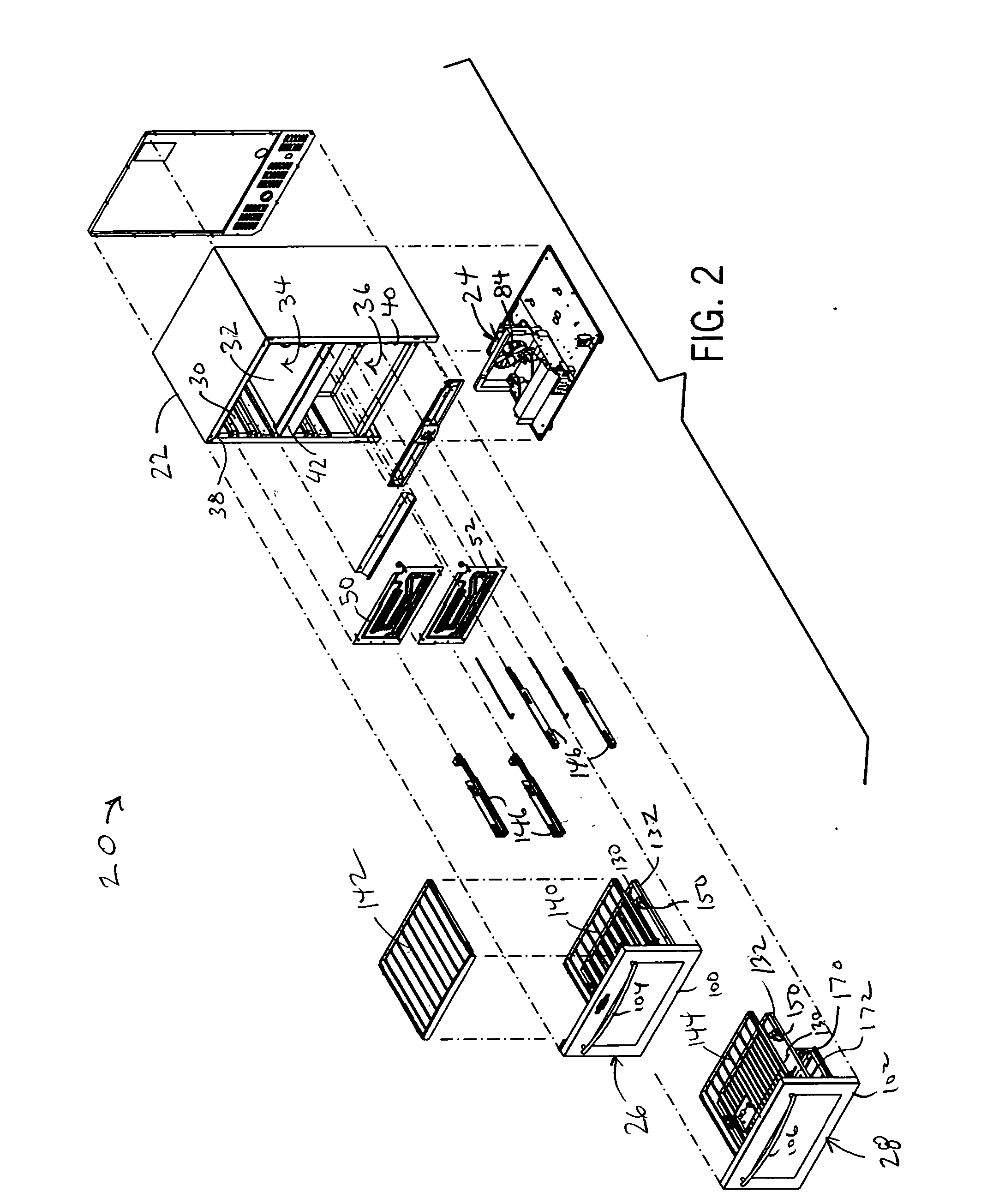
[0037] With reference to the figures, the present invention provides a cool storage unit 20 such as for food and beverages. The unit 20 includes an insulated cabinet 22 that is cooled by a refrigeration system 24 (see FIG. 11). The cabinet 22 houses one or more pull-out assemblies, such as pull-out assemblies 26 and 28, for supporting the stored items and allowing the items to be pulled out from the cabinet and accessed readily. In the preferred form discussed in detail herein, the unit 20 is a wine cooler unit for storing bottles of wine in a suitable, constant temperature environment. The cabinet holds the two pull-out assemblies 26 and 28 in a vertically stacked arrangement. While this is preferred, it should be noted that the cabinet 22 could hold only one pull-out assembly or more than two pull-out assemblies in a stacked or horizontal side-by-side arrangement. It should also be noted that the pull-out assemblies can include both racks and bin-like drawers.

[0038] Referring to...


PUM


Abstract

A wine cooler unit has a refrigerated cabinet housing two pull-out assemblies, each having a door panel and one or more wine racks. One rack can be mounted to the door panel, and one or more follower racks can be extended and retracted by movement of the door panel mounted rack, or by independent manual movement thereof. Two or more racks can be pulled out from the cabinet in a staggered or cascading fashion in which an upper rack extends from the cabinet to a lesser extent than a next lower rack to provide access to the bottles on each rack. The door panels can be made of a glass thermopane allowing visual inspection of the contents inside the cabinet. The cabinet can be cooled by a refrigeration system having two evaporators, which provide two independent cooling zones, one for each pull-out assembly. A capacitance-operated control can be provided under the glass front of one door panel for controlling the temperature zones inside the cabinet.

Description

CROSS-REFERENCE TO RELATED APPLICATIONS [0001] This application claims the benefit of U.S. provisional application Ser. No. 60 / 667,148 filed Mar. 31, 2005.STATEMENT OF FEDERALLY SPONSORED RESEARCH / DEVELOPMENT [0002] Not applicable. BACKGROUND OF THE INVENTION [0003] 1. Technical Field [0004] The present invention relates to refrigerated storage units, and in particular, to compact refrigeration units in which the storage space is defined by one or more pull-out sections. [0005] 2. Description of the Related Art [0006] Refrigerators and freezers for the cold storage of food and beverage items are well known. Many conventional units have one or more doors that are hinged to the front side of the cabinet. Food and beverages are ordinarily stored on shelves in the cabinet and the door(s) as well as in slide-out crisper drawers near the bottom of the cabinet. [0007] Increasingly people are desiring more variety and design flexibility for cool storage space in kitchens, bars and other roo...

Claims


Application Information

Patent Timeline
IPC IPC(8): F25D23/00F25D11/02
CPCA47B2088/023A47B2088/026F25D11/022F25D23/021F25D2700/04F25D31/007F25D2331/803F25D2400/361F25D25/025A47B88/75A47B2088/76
Inventor RAND, THOMAS W.MOYE, LAWRENCE D.DOBERSTEIN, ANDREW J.VAUGHN, JACK L.
Owner U LINE CORP A WI CORP
Learn More