
Method of registering different colours in flexography, and flexographic printer comprising a device for implementing said method

a technology of flexographic printing and flexography, which is applied in the direction of printing, other printing apparatus, rotary presses, etc., can solve the problems of affecting the accuracy of roller adjustment, hammer reading operations, and inability to measure the distance between

Inactive Publication Date: 2006-10-05
COMEXI GRP IND
View PDF7 Cites 10 Cited by
  • Summary
  • Abstract
  • Description
  • Claims
  • Application Information

AI Technical Summary

Benefits of technology

[0017] Thus, the method and device employed in this invention allow the register adjustment of various colours in flexography in a more economical manner than with currently known methods, because only the inclusion of an optical sensor is required, which is significantly more economical than video image acquisition equipments employed up to now, and takes advantage of the angular position detectors and control devices currently existing in many flexographic printers. Moreover, the method of this invention allows the register adjustment operations to be carried out in less time and with less waste of material to be printed since the optical sensor can be placed next to the printing zone, for example, next to the printing group placed furthest downstream. It also has the advantage of not requiring any specific angular pre-positioning of the printing rollers because the marks are printed and read individually and the adjustment operations are accurately performed whatever the initial degree of angular misadjustment. In addition, since the distance between marks is not taken into account, but instead, the position of each mark within the printing length, there is practically no loss of precision due to print material stretching, which is usual in state of the art devices.

Problems solved by technology

One inconvenience of this present system is that, since all the marks are printed at the same time, it is necessary to perform an initial pre-positioning of all the printing rollers within certain tolerances to prevent the various marks printed by them being superposed, which would hamper reading operations and make it impossible to measure the distances between them.
In addition, the distances between the marks could be so large that they could be affected by possible stretching of the material to be printed which, in turn, would affect the roller adjustment accuracy.
Moreover, video image acquisition equipment is relatively expensive and requires flame-proofing, which is also costly if it is to be installed close to the printing groups.
However, this position far from the printing rollers involves a loss of printing time and material to be printed during the register adjustment operation.

Method used


Image

  • Method of registering different colours in flexography, and flexographic printer comprising a device for implementing said method
  • Method of registering different colours in flexography, and flexographic printer comprising a device for implementing said method
  • Method of registering different colours in flexography, and flexographic printer comprising a device for implementing said method

Examples


Embodiment Construction

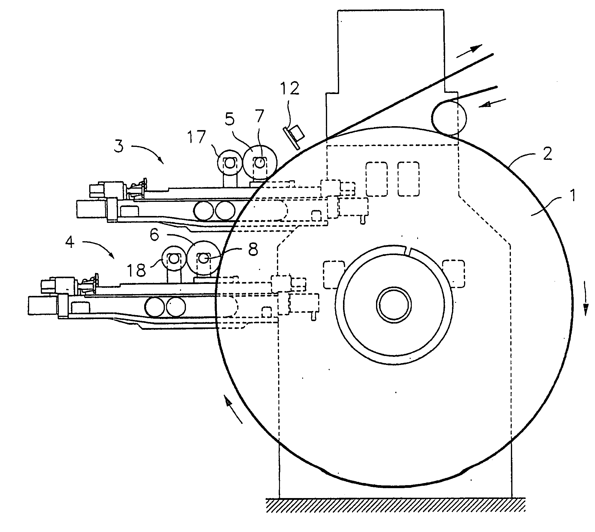
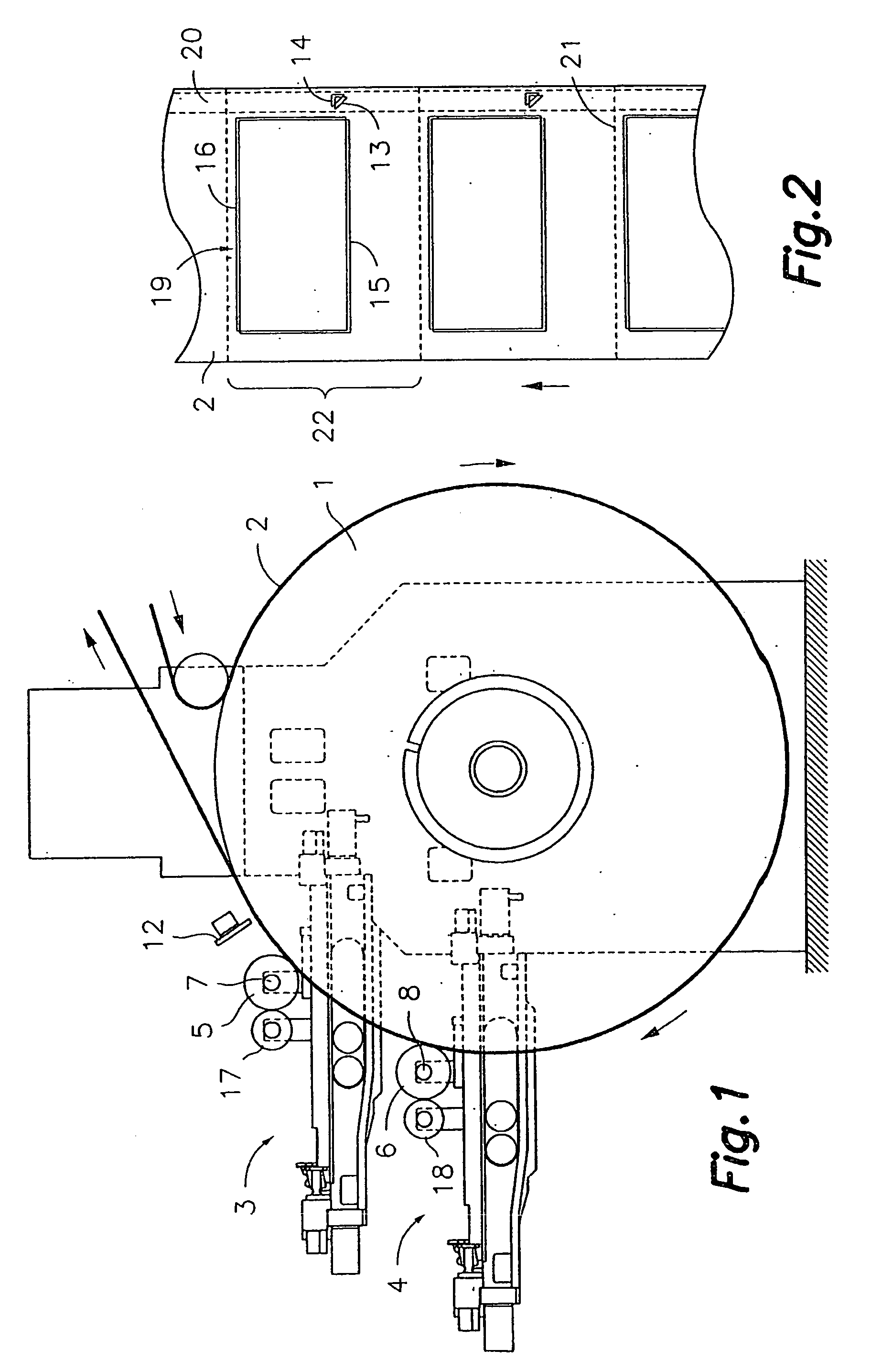
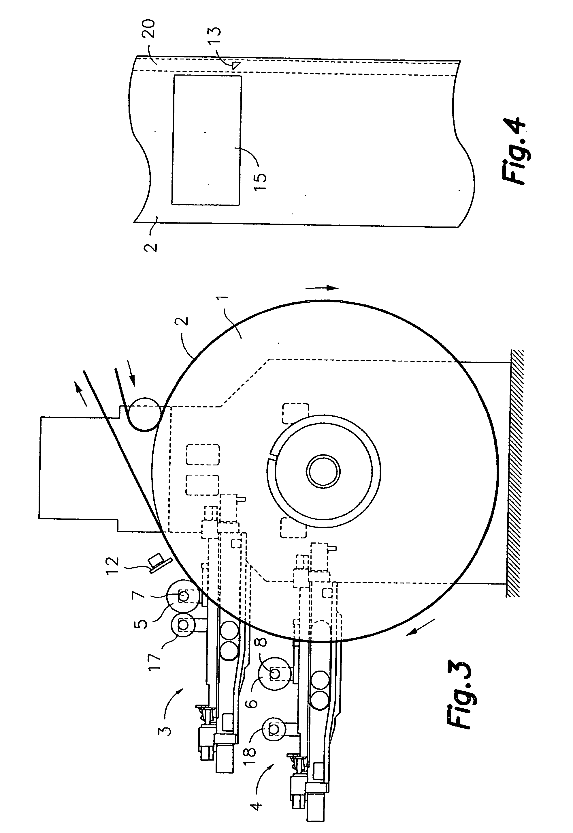
[0026] First referring to FIG. 1, it shows a flexographic printer of the type consisting of a central rotating supporting drum 1, supporting the material to be printed 2 in the form of a continuous strip that moves in the direction indicated by the arrows next to the peripheral surface of the drum 2 as it rotates. Next to the supporting drum 2 are the first and second printing groups 3, 4, which include the respective first and second printing rollers 5, 6 and respective first and second ink rollers 17, 18. A printing configuration 15a, 16a (FIG. 7) is arranged at the periphery of each printing roller 5, 6, which constitutes the matrix or stencil of part of the motif to be printed. The cited first and second printing groups 3, 4 are configured, arranged and selectively driven to change between a printing position, in which the corresponding first and / or second printing rollers 5, 6 and consequently, the corresponding printing configuration, is in contact with said material to be pri...


PUM


Abstract

A method of registering various colours in flexography, and a flexographic printer comprising a device for implementing the method are provided. The printer comprises at least one supporting drum with at least first and second printing rollers and an optical sensor, downstream from the rollers. The method comprises consecutively printing first and second marks with the first and second rollers, using the sensor to generate first and second position signals that are representative of the positions of the first and second marks within a printing length and to generate adjustment signals by comparison of the second position signal with the first position signal, taken as reference, or the first and second position signals with a pre-established position signal. The positions of rollers are adjusted based on the adjustment signals.

Description

FIELD OF THE INVENTION [0001] In general, this invention concerns to a method of registering various colours in flexography, and more specifically, to the use of a chromatic optical sensor to detect the positions of marks printed by various printing rollers and the carrying out of printing roller position adjustments from said detection. This invention also concerns to a flexographic printer with a device for the implementation of said method. TECHNICAL BACKGROUND [0002] Flexographic printers use a large number of printing groups to print the various superposed parts of an image onto a sheet material, where the various superposed parts together form the desired complete image. Generally, each of the various parts corresponds to one colour and the superposition of the various parts of the various colours produces a final image with a chromatic richness that is much higher than that of the limited colours of the component parts. The accuracy in the superposition of the cited parts is ...

Claims


Application Information

Patent Timeline
IPC IPC(8): B41M1/14B41F13/02B41F33/00
CPCB41F13/025B41P2200/12B41F33/0081
Inventor CADILLACH, FELIP FERRER
Owner COMEXI GRP IND
Learn More