Inclusive single-use cooking apparatus

a single-use, cooking technology, applied in the direction of lighting and heating equipment, domestic stoves or ranges, climate sustainability, etc., can solve the problem that grilling is not particularly feasible for the last tim

Inactive Publication Date: 2006-10-05
SOLOGEAR
View PDF97 Cites 21 Cited by
  • Summary
  • Abstract
  • Description
  • Claims
  • Application Information

AI Technical Summary

Benefits of technology

[0006] In one aspect, the invention provides a cooking assembly comprising a main housing, a fuel vessel assembly containing fuel and a cooking grate. The main housing has side walls, a bottom wall, an outer rim and an inside and outside. The cooking grate comprises a metal sheet that has a top side, a bottom side, a plurality of grate peaks and grate valleys and a plurality of apertures. Grease drip initiation tabs can broader the apertures of the cooking grate to prevent grease from wicking to the underside of the cooking grate and dropping on the flames of the fuel. The cooking grate can also contain a thermal feedback label, which can be affixed to a thermal insulator positioned between the label and the metal sheet. The thermal feedback label can indicate to the user the temperature of the grill in operation. In one embodiment the cooking grate rests on the outer rim of the main housing. The cooking assembly can also have an insulating wrap, suitably cardboard, that connects to the main housing. The insulating wrap can have grip sections that allows the user to position the cooking assembly.
[0008] In one embodiment, the fuel vessel assembly comprises a fuel vessel having side walls and a bottom, the side walls defining an opening. In this opening the fuel is held by the fuel vessel. In one embodiment the fuel vessel also has a lip, on which a combustible sealing film is attached. This combustible sealing film covers the opening of the fuel vessel and is suitably impervious to vapor loss to prevent loss of the fuel. In another embodiment, the opening of the fuel vessel is covered by a removable sealing film. This sealing film is also suitably impervious to vapor loss to prevent loss of the fuel. The fuel vessel assembly can also can contain a porous membrane that can be positioned between the fuel and the sealing film. The fuel vessel assembly can also contain a combustion enhancing strip that is in contact with the combustible sealing film. Additionally, the fuel vessel assembly can also include a restrictor plate that has a top side, a bottom side and an aperture. The restrictor plate is positioned over the top side of the sealing film of the fuel vessel. The restrictor plate can be connected directly to the fuel vessel, or can be supported by the main housing. Suitably the aperture of the restrictor plate is narrower than the width of the opening of the fuel vessel. This arrangement can help in controlling the combustion rate of the fuel. The restrictor plate can also contain a pair of legs located on the end sides of the plate. In one embodiment the legs are attached to the bottom of the main housing. In another embodiment the legs can be attached to the outer rim of the main housing. The length of the support legs in either of these embodiments can be such that when the restrictor plate is attached to the fuel vessel, the bottom of the fuel vessel is suspended off of the bottom of the main housing, providing an insulating air gap between the bottom of the fuel vessel and the bottom of the main housing. When the legs of the restrictor plate are attached to the bottom of the main housing, the legs should be longer than the side walls of the fuel vessel to provide this air gap.
[0010] In other embodiments of the invention, the cooking assembly further comprises an ignition sheet which is positioned between the fuel vessel or vessels, and the cooking grate. This ignition sheet can have a tab that can extend outwardly from the main housing by way of an air ventilation aperture in the side wall of the housing. The tab allows for a user to ignite the ignition sheet, which in turn ignites the combustible sealing film, and in turn the fuel of the fuel vessel assembly. By this design a user can ignite the fuel of the cooking assembly without having to remove the cooking grate and directly accessing the fuel vessel of vessels.

Problems solved by technology

Due to the breadth of required items, grilling is not particularly feasible for last-minute planners or those that want to impulsively grill.

Method used


Image

  • Inclusive single-use cooking apparatus
  • Inclusive single-use cooking apparatus
  • Inclusive single-use cooking apparatus

Examples


Embodiment Construction

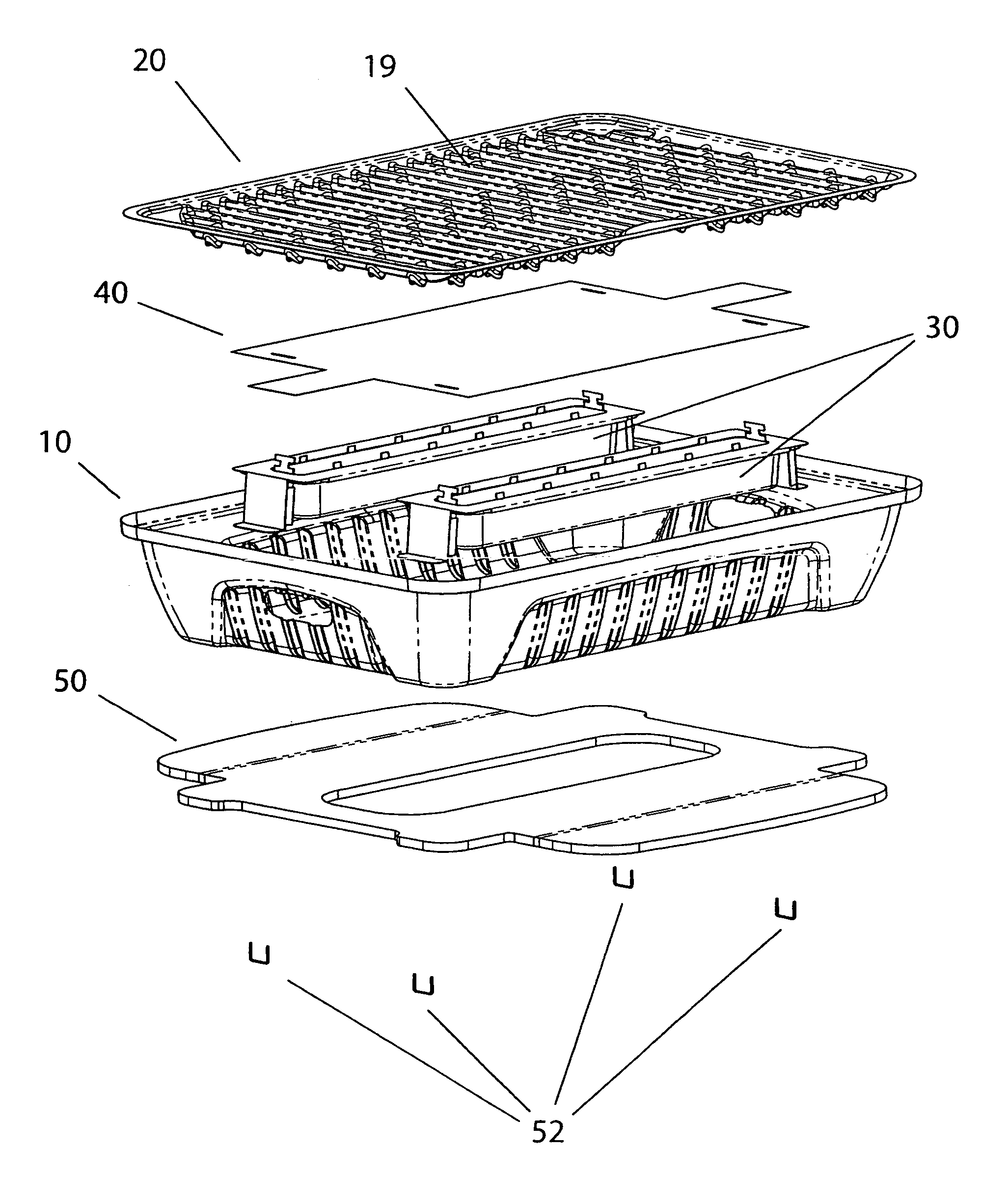
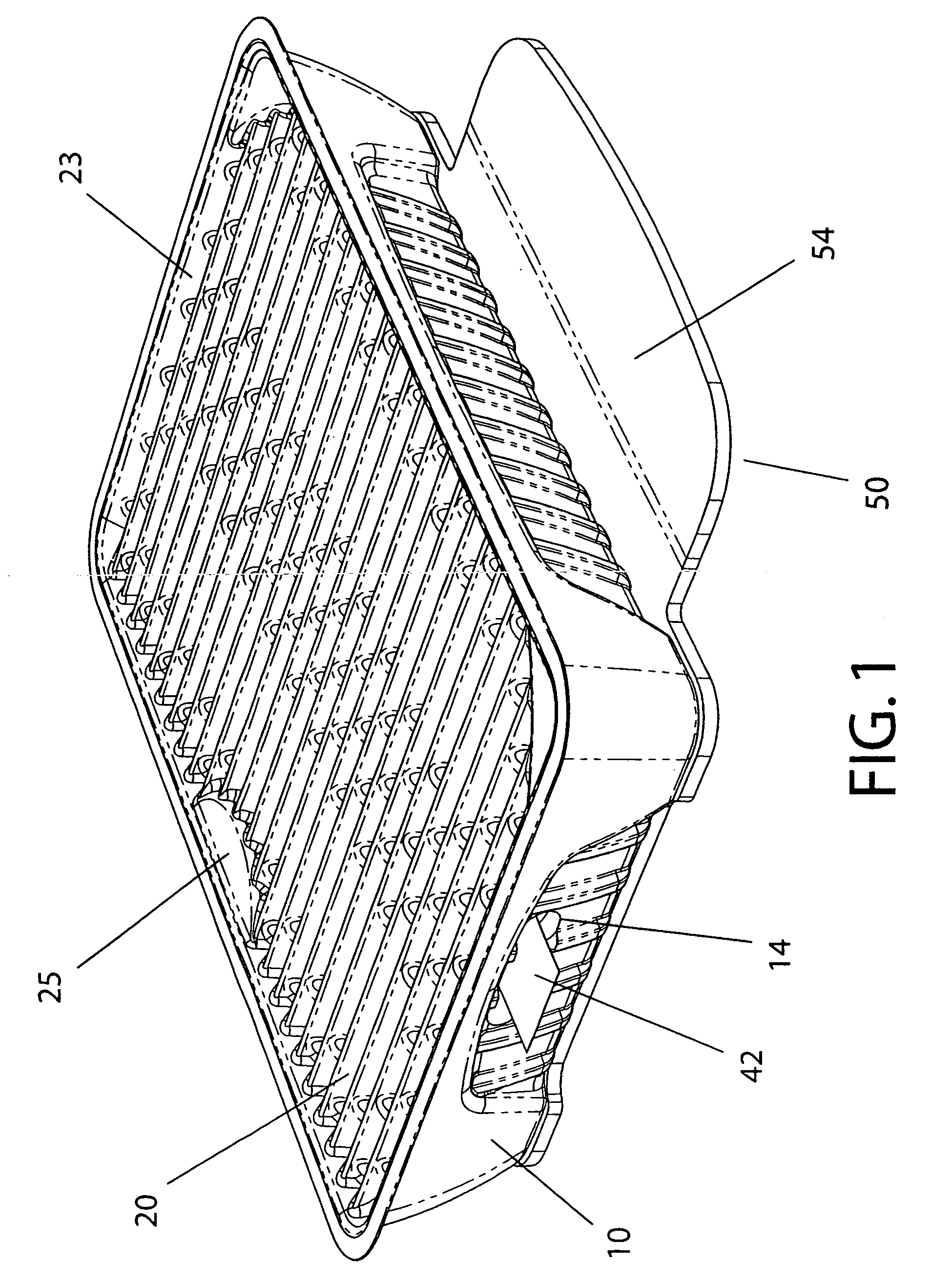
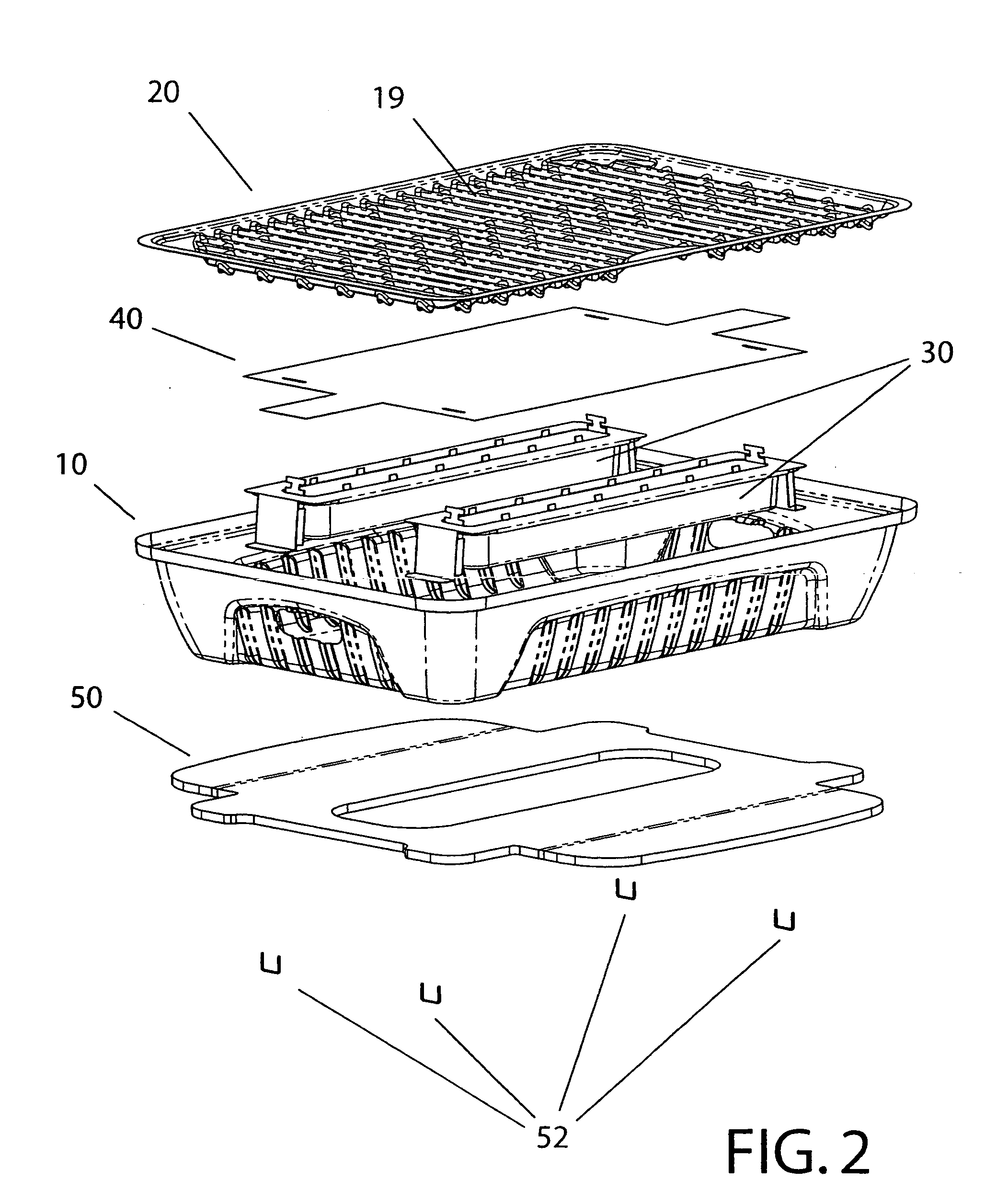
[0051] The present invention provides a single-use cooking assembly that utilizes a non-charcoal fuel source and is all-inclusive in nature. Suitably, the cooking assembly requires no additional components beyond food for a complete cooking session. Suitably, the fuel utilized is a gelled alcohol, which is clean-burning, inexpensive and requires the use of no intermediate tinder material to achieve self-sustaining combustion. In this way, the user may directly ignite the base fuel and does not have to wait for the heat source to reach a suitable temperature to begin cooking, which is otherwise typical with more traditional wood or charcoal fuels. This allows the user to experience very little delay between ignition and actual cooking.

[0052] In one embodiment, the fuel is housed within two thin-gauge metal fuel vessel assemblies. Each assembly comprises a fuel vessel, each fuel vessel being sealed with a metallized combustible and impermeable polymer film, referred to as the combust...


PUM


Abstract

A single-use cooking apparatus utilizing a non-charcoal fuel source that is all-inclusive in nature; providing all tools, accessories and ignition means necessary for a complete cooking session. The cooking apparatus may be suitably fueled with a semi-solidified or gelled alcohol fuel, which provides immediate and controlled heat, a finite and predictable cooking time period, and rapid cool-down due to the invention's minimal mass and high material efficiency. The device is manufactured with sufficient economy to justify complete discard at the conclusion of the cooking session.

Description

CROSS-REFERENCE TO RELATED APPLICATIONS [0001] This application claims the benefit of the priority date of U.S. Provisional Patent Application No. 60 / 668,380, filed Apr. 5, 2005, and U.S. Provisional Patent Application No. 60 / 697,216, filed Jul. 6th, 2005, the applications incorporated by reference in their entireties.BACKGROUND OF THE INVENTION [0002] The barbeque grill has become about as ubiquitous as the kitchen stove in modern American households. Today, about 76% of United States households own a barbeque grill and over 66 million Americans grill per year, according to the Barbecue Industry Association (2001). It is conservatively estimated that in the U.S. alone, there are over three billion “grilling events” per year. [0003] Despite the broad appeal and general advantages of grilling, there remain some inherent shortcomings within certain niches of this multi-billion dollar industry. Grilling requires a fair amount of planning and relies on a variety of support accessories a...

Claims


Application Information

Patent Timeline
Patent Type & Authority Applications(United States)
IPC IPC(8): F24B1/20
CPCY02B40/166A47J37/0768Y02B40/00
Inventor SORENSON, CHAD M.FRANCHINO, DAVID C.SCHWEIGER, MARKBUSH, TOM
Owner SOLOGEAR
Why Eureka
Try Eureka