Gas conserving device

a gas conserving device and gas technology, applied in the direction of valves, respirators, operating means/releasing devices, etc., can solve the problems of limited oxygen inside the tank, oxygen stored under pressure may create a hazard if the storage vessel, and general ill-suited portability of oxygen concentrators, etc., to overcome the shortcomings of conventional oxygen conservers and reduce power

Active Publication Date: 2006-10-05
PHILIPS RS NORTH AMERICA LLC
View PDF19 Cites 59 Cited by
  • Summary
  • Abstract
  • Description
  • Claims
  • Application Information

AI Technical Summary

Benefits of technology

[0014] Accordingly, it is an object of the present invention to provide an electronic oxygen conserving device that overcomes the shortcomings of conventional oxygen conservers. This object is achieved according to one embodiment of the present invention by providing an electronic oxygen conserving device that includes a valve body having a valve seat disposed in the valve body, and a valve element disposed within the valve body. A portion of the valve element seats against the valve seat when the valve element is in a closed position, and is spaced apart from the seat when to the valve element is in an open position. A permanent magnet is disposed in the valve body and is adapted to magnetically engage the valve element when the valve element is in the open position to maintain the valve element in the open position. An energy source delivers a first energy to the valve element, the permanent magnet, or both to move the valve element to the open position. The energy source also delivers a second energy to valve element, the permanent magnet, or both to move the valve element to the closed position. A sensor monitors a characteristic of a user indicative of respiration. The electronic oxygen conserving device includes a gas flow controller having a plurality of gas flow delivery settings corresponding to a plurality of predetermined gas flow rates / volumes. Finally, a controller controls the energy source based on the gas flow delivery setting and an output of the sensor.
[0015] In a second embodiment, this object is achieved by providing a gas conserving device that includes a breath sensor adapted to detect inhalation by a patient, a slave valve, and a pilot valve. The slave valve has an open position for providing a flow of gas from a gas source to a patient, and a closed position for ceasing the flow of gas to the patient. The pilot valve communicates with the slave valve to control a position of the slave valve. An energy source provides a first energy to the pilot valve when to the breath sensor sensing detects inhalation by such a patient. As a result, the pilot valve causes the slave valve to the open position when the slave valve receiving the first energy from the energy source.
[0016] The present invention provides a gas conserving device that operates at a very lower power. For example, the present invention uses 5.85E-06 Watts-seconds or less do deliver twelve milliliters or more of or oxygen during a single breath or pulse dose. This power requirement is independent of the volume of oxygen delivered during that breath of pulse dose, the time that the valve is open to deliver the dose of oxygen, or the flow setting selected by the user.
[0017] These and other objects, features, and characteristics of the present invention, as well as the methods of operation and functions of the related elements of structure and the combination of parts and economies of manufacture, will become more apparent upon consideration of the following description and the appended claims with reference to the accompanying drawings, all of which form a part of this specification, wherein like reference numerals designate corresponding parts in the various figures. It is to be expressly understood, however, that the drawings are for the purpose of illustration and description only and are not intended as a definition of the limits of the invention. As used in the specification and in the claims, the singular form of “a”, “an”, and “the” include plural referents unless the context clearly dictates otherwise.

Problems solved by technology

While suitable for their intended purpose, oxygen concentrators are generally ill-suited for portability due the relatively bulky gas compressor and sieve beds needed to generate a practical quantity of oxygen, and, therefore, are not intended for use with an ambulatory individual.
One disadvantage of compressed oxygen systems is that oxygen is stored under pressure may create a hazard if the storage vessel is damaged, which can occur if it is dropped, bumped, punctured, etc.
Thus, they are limited in how long the oxygen inside the tank will last depending on the prescribed flow rate and the type / size of the tank.
These systems have limited utilization due to the low LOX capacity of the portable delivery apparatus and the administered LOX flow rate.
Furthermore, even when not in use, the LOX within the portable delivery apparatus evaporates at a typical rate of one pound per day, empting the portable delivery apparatus LOX supply over time even if it is not used.
Consequently, a disadvantage of a portable LOX system includes the requirement that the user must return home regularly, such as by the end of the day, to refill the portable delivery apparatus from the home stationary LOX storing canister.
A limiting factor in the utilization of compressed gas and LOX is the small quantity of oxygen stored by these respective systems.
In order to ensure the portability of these systems, they tend to be as small as possible, hence limiting the oxygen capacity available for therapeutic utilization.
Accordingly, one of the major drawbacks of an electrical oxygen conserving device is that the power supply, namely the battery or batteries, runs down relatively quickly, necessitating frequent changing of the batteries and constant monitoring of the battery charge.
For patients that are elderly or infirm, this maintenance requirement is difficult, if not impossible, and / or burdensome.
While suitable for its intended purpose, this design has two drawbacks.
An additional drawback to this design is that the circuitry requires a continuous current to be supplied to the control logic, which undersirably limits the useful life of a power source.
A primary drawback of a typical pneumatic oxygen conserving device is the sensitivity of the master diaphragm to an individual's inhalation pressure.
Likewise, there may be a time delay between the initial inhalation of the patient and the operation of the pneumatic system before oxygen is permitted to flow to the patient.
These drawbacks are the result of a purely mechanical system for controlling the flow of oxygen.
This results in a complex interaction of the components, which may jeopardize the reliability of the conservation device.
Also, the addition components may result in a bulky and costly device.

Method used


Image

  • Gas conserving device
  • Gas conserving device
  • Gas conserving device

Examples


Embodiment Construction

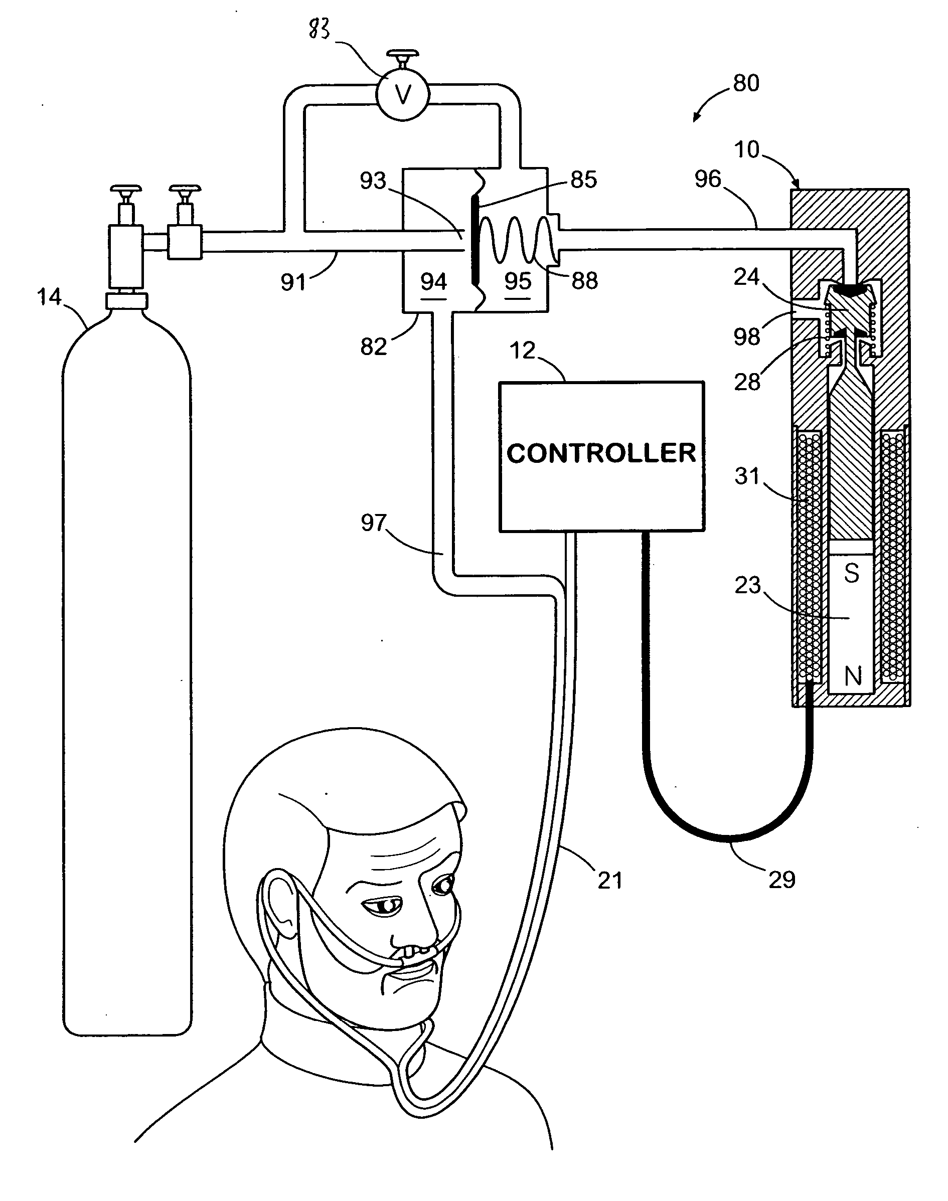
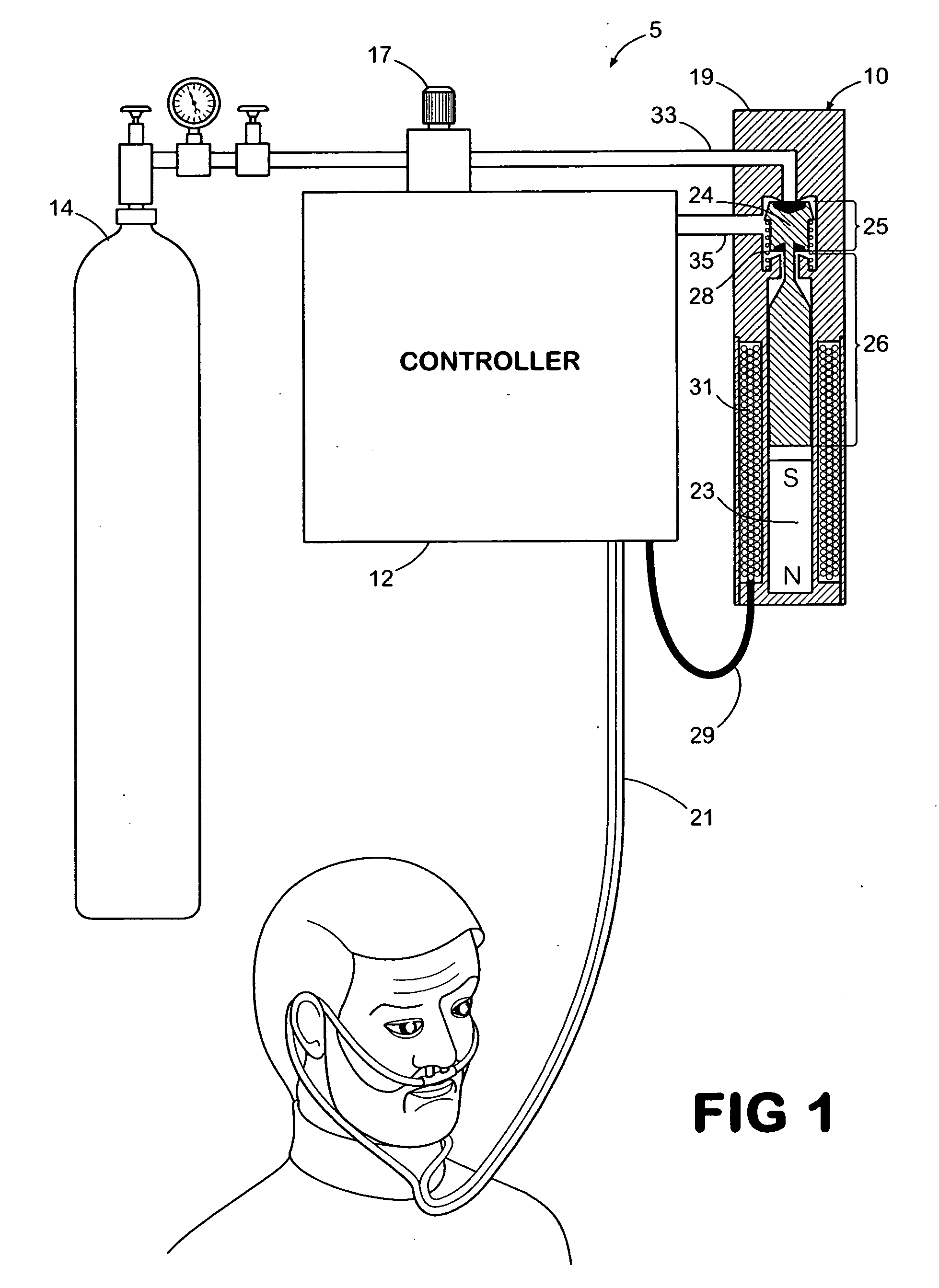
[0023] Referring now to the drawings, in which like numerals represent like components or steps throughout the several views, FIG. 1 illustrates an electronic oxygen conserving device 5 according to an embodiment of the present invention. Electronic oxygen conserving device 5 is for an individual to use in combination with an oxygen storage container 14 and includes an oxygen conserving controller 12 and an oxygen regulating valve 10. In operation, oxygen storage container 14 provides oxygen to oxygen conserving controller 12, which includes a plurality of oxygen flow settings, e.g., a continuous oxygen flow setting and a conserving (pulse) oxygen flow setting. When oxygen conserving controller 12 is set to the conserving (pulse) oxygen flow setting, the flow of oxygen is provided from oxygen conserving controller 12 to oxygen regulating valve 10 and, subsequently, to a nasal cannula 21. It is to be understood that any conventional oxygen delivery patient interface, such as a mask, ...


PUM


Abstract

An electronic oxygen conserving device for controlling a flow of oxygen from an oxygen storage container to a user. When a conserve setting is selected, a flow of oxygen travels through an oxygen regulating valve that has an open state and a closed state. A temporary electrical charge or current is provided to the oxygen regulating valve during the initial inhalation of oxygen by an individual, opening the regulating valve opens to delivery oxygen to the user. The oxygen regulating valve remains open even after termination of the electric current. After a predetermined timed delivery dose or upon exhalation by the individual, a subsequent temporary electric charge or current is provided to oxygen regulating valve, closing the regulating valve closes to prevent delivery of oxygen to the user, thus conserving oxygen. The oxygen regulating valve remains closed even after termination of the subsequent electric current.

Description

BACKGROUND OF THE INVENTION [0001] 1. Field of the Invention [0002] This invention relates to respiratory gas delivery devices, and, more particularly, to a gas conserving device that utilizes an electronically controlled latching valve to regulate the flow of gas to a user. [0003] 2. Description of the Related Art [0004] It is well known to deliver a flow of respiratory gas to a user in the form of supplemental oxygen. The delivery of supplemental oxygen to a patient is typically prescribed for individuals suffering from pulmonary / respiratory problems. The prescription and delivery of supplemental oxygen is undertaken to ensure that sufficient oxygen levels are being received by the patient. Situations in which supplemental oxygen may be prescribed include individual suffers from chronic obstructive pulmonary disease (COPD), asthma, diseased or damaged lungs. [0005] The delivery of supplemental oxygen may be provided utilizing one of three predominant methods. For non-ambulatory pa...

Claims


Application Information

Patent Timeline
Patent Type & Authority Applications(United States)
IPC IPC(8): A62B7/04A61M16/00F16K31/26
CPCA61M16/0666A61M2016/0021A61M2016/0027A61M16/0677F16K31/0627A61M16/0672A62B7/04A61M2202/0208A61M2202/03A61M2202/0007
Inventor HOLDER, GARY N.
Owner PHILIPS RS NORTH AMERICA LLC
Why Eureka
Try Eureka