
Codoped Direct-Gap Semiconductor Scintillators

a direct-gap semiconductor and scintillator technology, applied in the field of scintillators, can solve the problems of reducing the luminosity at room temperature, limiting the use of cryogenic temperatures, and no known inorganic scintillators are both bright and fast, and achieve the effect of fast bright inorgani

Inactive Publication Date: 2006-10-05
RGT UNIV OF CALIFORNIA
View PDF5 Cites 14 Cited by
  • Summary
  • Abstract
  • Description
  • Claims
  • Application Information

AI Technical Summary

Benefits of technology

The codoped scintillators provide exceptional detection efficiency, response time, and energy resolution, enabling septaless time-of-flight PET and improving imaging capabilities in medical and other fields.

Problems solved by technology

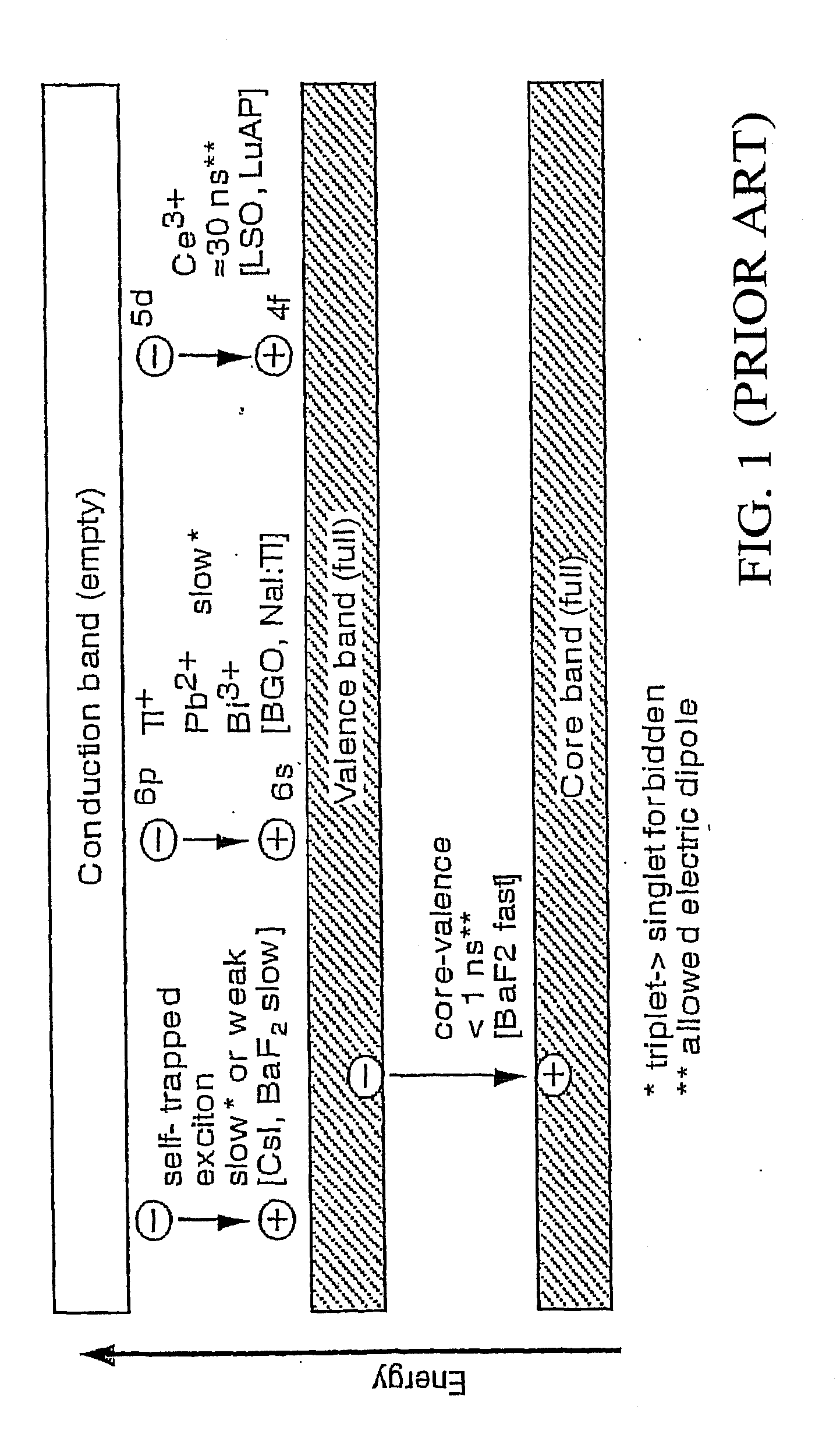
Unfortunately, no known inorganic scintillator is both bright and fast.
Direct-gap semiconductors are fast, luminous scintillators when cooled to cryogenic temperatures, but have greatly reduced luminosity at room temperature due to carrier trapping on non-radiative centers (crystal defects and impurities).
The need for cryogenic temperatures limits their use.
However, PET has been limited by the timing and energy resolution of available scintillators.

Method used


Image

  • Codoped Direct-Gap Semiconductor Scintillators
  • Codoped Direct-Gap Semiconductor Scintillators
  • Codoped Direct-Gap Semiconductor Scintillators

Examples


Embodiment Construction

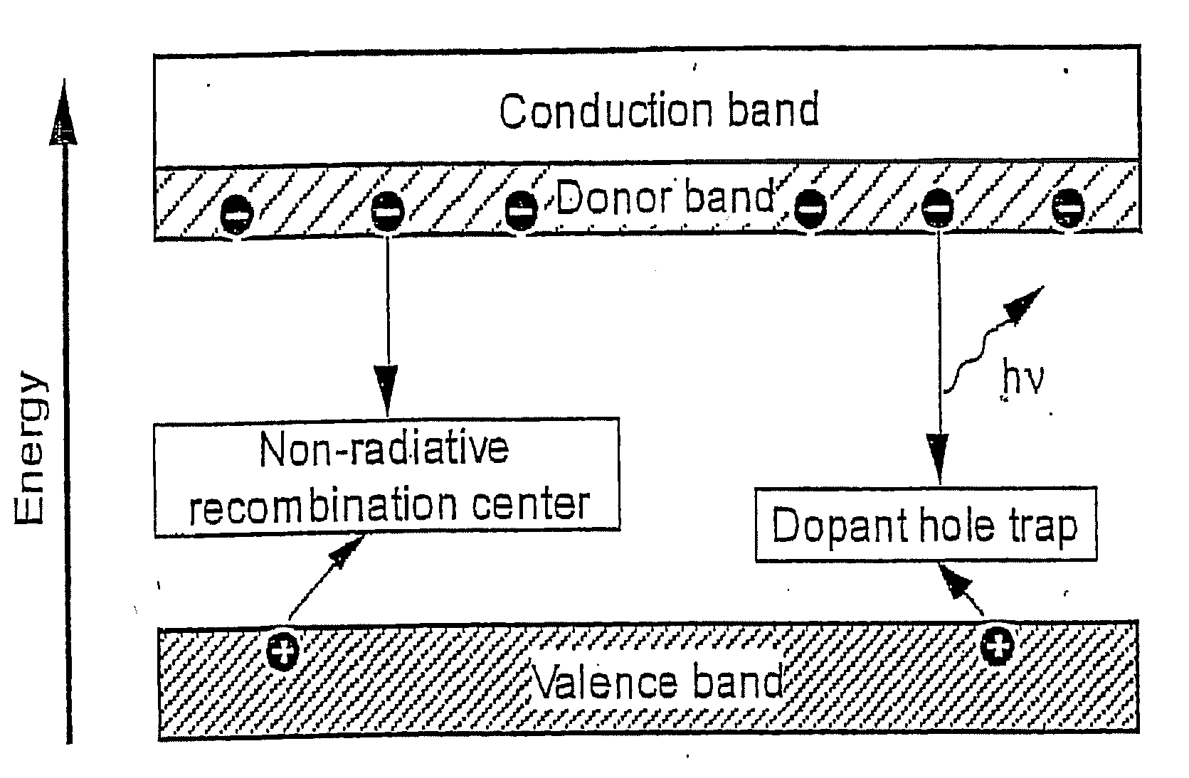
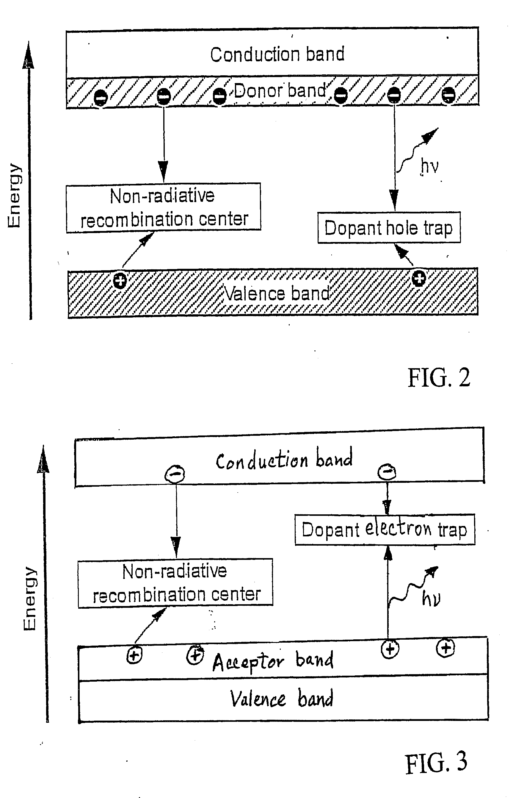
[0020] The invention is an improved inorganic scintillator based on a direct-gap semiconductor into which two different impurity atoms or dopants are introduced. By selecting one foreign atom to provide a carrier band and the other foreign atom to provide for efficient trapping of the other carrier, rapid radiative recombination occurs, providing a fast luminous scintillation mechanism.

[0021] The codoped direct-gap semiconductor scintillators work on the basis of radiative electron-hole recombination. One dopant provides an abundant supply of charge carriers of one type (electrons or holes). The other dopant promptly and efficiently traps the other type of charge carrier (holes or electrons, respectively) produced by the ionizing radiation. The first dopant is a neutral donor or acceptor to provide an abundant supply of either electrons or holes. The second dopant can be an ionized acceptor atom (to trap holes), an ionized donor atom (to trap electrons), or an isoelectronic trap (o...


PUM

PropertyMeasurementUnit
mole %aaaaaaaaaa
fwhmaaaaaaaaaa
concentrationaaaaaaaaaa

Abstract

Fast, bright inorganic scintillators at room temperature are based on radiative electron-hole recombination in direct-gap semiconductors, e.g. CdS and ZnO. The direct-gap semiconductor is codoped with two different impurity atoms to convert the semiconductor to a fast, high luminosity scintillator. The codopant scheme is based on dopant band to dopant trap recombination. One dopant provides a significant concentration of carriers of one type (electrons or holes) and the other dopant traps carriers of the other type. Examples include CdS:In,Te; CdS:In,Ag; CdS:In,Na; ZnO:Ga,P; ZnO:Ga,N; ZnO:Ga,S; and GaN:Ge,Mg.

Description

CROSS-REFERENCE TO RELATED APPLICATIONS [0001] This application claims priority of Provisional Application Ser. No. 60 / 411,491 filed Sep. 16, 2002, which is herein incorporated by reference.STATEMENT OF GOVERNMENTAL SUPPORT [0002] The United States Government has rights in this invention pursuant to Contract No. DE-AC03-76SF00098 between the United States Department of Energy and the University of California.BACKGROUND OF THE INVENTION [0003] The invention relates to scintillators, and more particularly to fast, bright inorganic scintillators based on direct-gap semiconductors. [0004] Inorganic scintillators have been used as radiation detectors for x-rays, gamma rays, and neutrons, for over a century. The history of inorganic scintillators is described in S. E. Derenzo et al., “The Quest for the Ideal Inorganic Scintillator,” Nuclear Instruments and Methods in Physics Research A 505 (2003) 111-117, which is herein incorporated by reference. [0005] Table I lists the best available p...

Claims


Application Information

Patent Timeline
Patent Type & Authority Applications(United States)
IPC IPC(8): G01T1/20C09K11/08C09K11/56
CPCC09K11/565
Inventor DERENZO, STEPHEN E.BOURRET-COURCHESNE, EDITHWEBER, MARVIN J.KLINTENBERG, MATTIAS K.
Owner RGT UNIV OF CALIFORNIA
Learn More