Isolation gasket, system and method of manufacture

Inactive Publication Date: 2006-10-05
CORROSION CONTROL CORP PIKOTEK
View PDF8 Cites 49 Cited by
  • Summary
  • Abstract
  • Description
  • Claims
  • Application Information

AI Technical Summary

Benefits of technology

[0006] It is feature and advantage of the present invention to provide a new and useful isolation gasket and seal system that provides an interface between flange connections and flow line applications.
[0007] It is another feature and advantage of the present invention to provide an isolation gasket that helps eliminate false readings when a flange is undergoing hydrostatic testing.
[0008] It is another feature and advantage of the present invention to provide an isolation gasket that is suitable for use in fire safe applications.
[0009] To achieve the stated and other features, advantages and objects, embodiments of the invention provide an isolation device for use between joined pieces in a flow line that is operative for fluid passage therethrough without leakage comprising, for example, a flat metal plate, such as a flat annular metal plate, having opposing side surfaces and an opening formed in the metal plate to allow passage of fluid therethrough. In addition, a sheet of dielectric material is disposed on at least one side surface of the metal plate, and preferably on both side surfaces of the metal plate, for example, by laminating the sheet to either or both side surfaces of the metal plate. Further, at least one groove is formed on the side surface or surfaces on which the sheet of dielectric material is disposed which penetrates through the dielectric material and into the metal plate and which extends completely around the opening formed in the metal plate, and a layer of insulating material, as well as a seal element, are disposed in each of the grooves.
[0010] In embodiments of the invention in which the layers

Problems solved by technology

Additionally, the transfer of some fluids and/or the nature of fluids can result in the build up of electrical charge across the flange.
Electrical discharges caused by difference in electrical potential create two issues.
On one hand, electrical discharges can damage the integrity of the seal device.
There is also the danger that an electrical discharge will create a spark that can ignite a flammable or explosive fluid in the flow line.
Therefore, flow line sealing systems face numerous challenges.
For example, many materials which resist c

Method used


Image

  • Isolation gasket, system and method of manufacture
  • Isolation gasket, system and method of manufacture
  • Isolation gasket, system and method of manufacture

Examples


Embodiment Construction

[0029] Reference will now be made in detail to embodiments of the invention, one or more examples of which are illustrated in the accompanying drawings. Each example is provided by way of explanation of the invention, not as a limitation of the invention. It will be apparent to those skilled in the art that various modifications and variations can be made in the present invention without departing from the scope or spirit of the invention. For example, features illustrated or described as part of one embodiment can be used on another embodiment to yield a still further embodiment. Thus, it is intended that the present invention cover such modifications and variations that come within the scope of the invention.

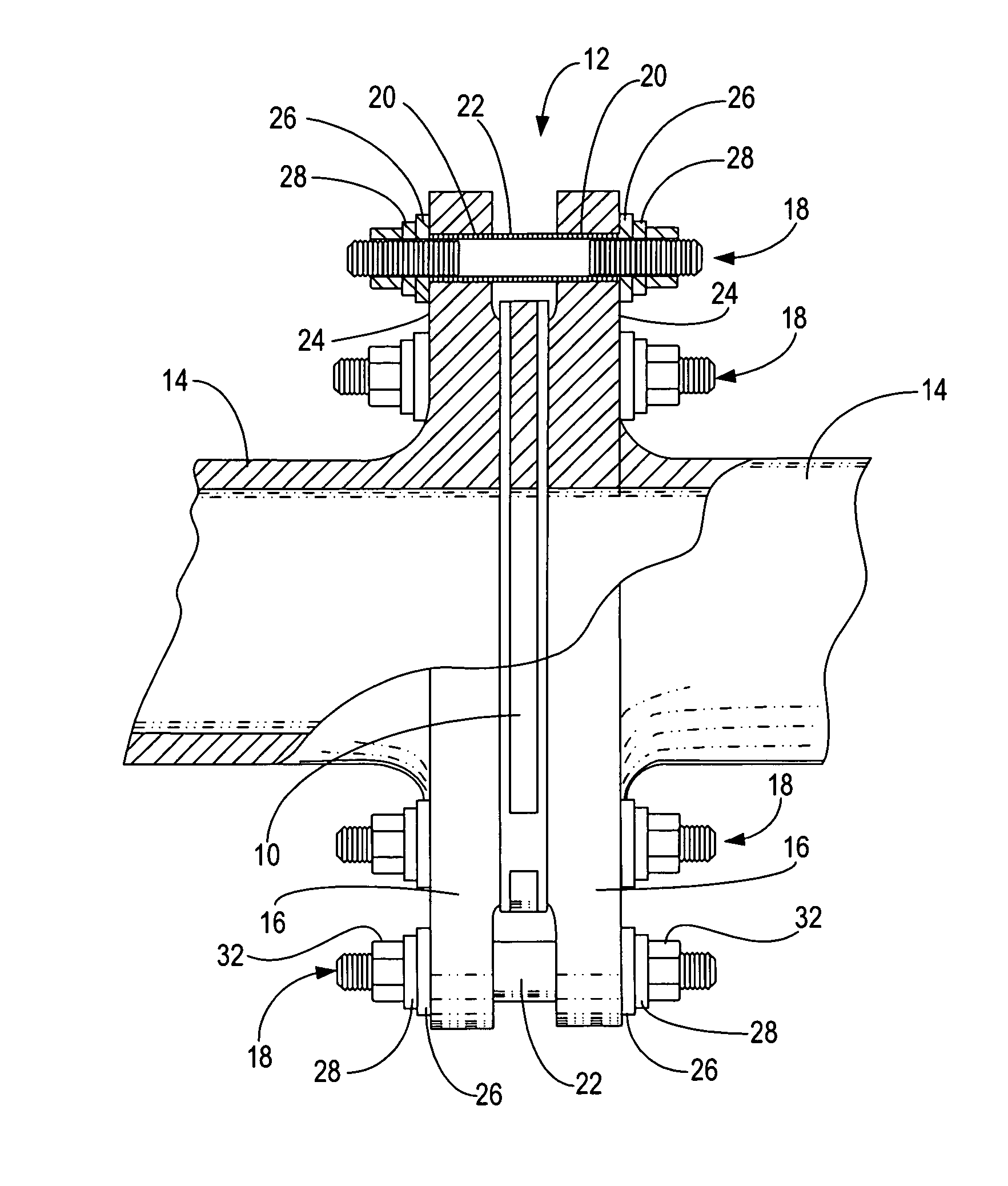
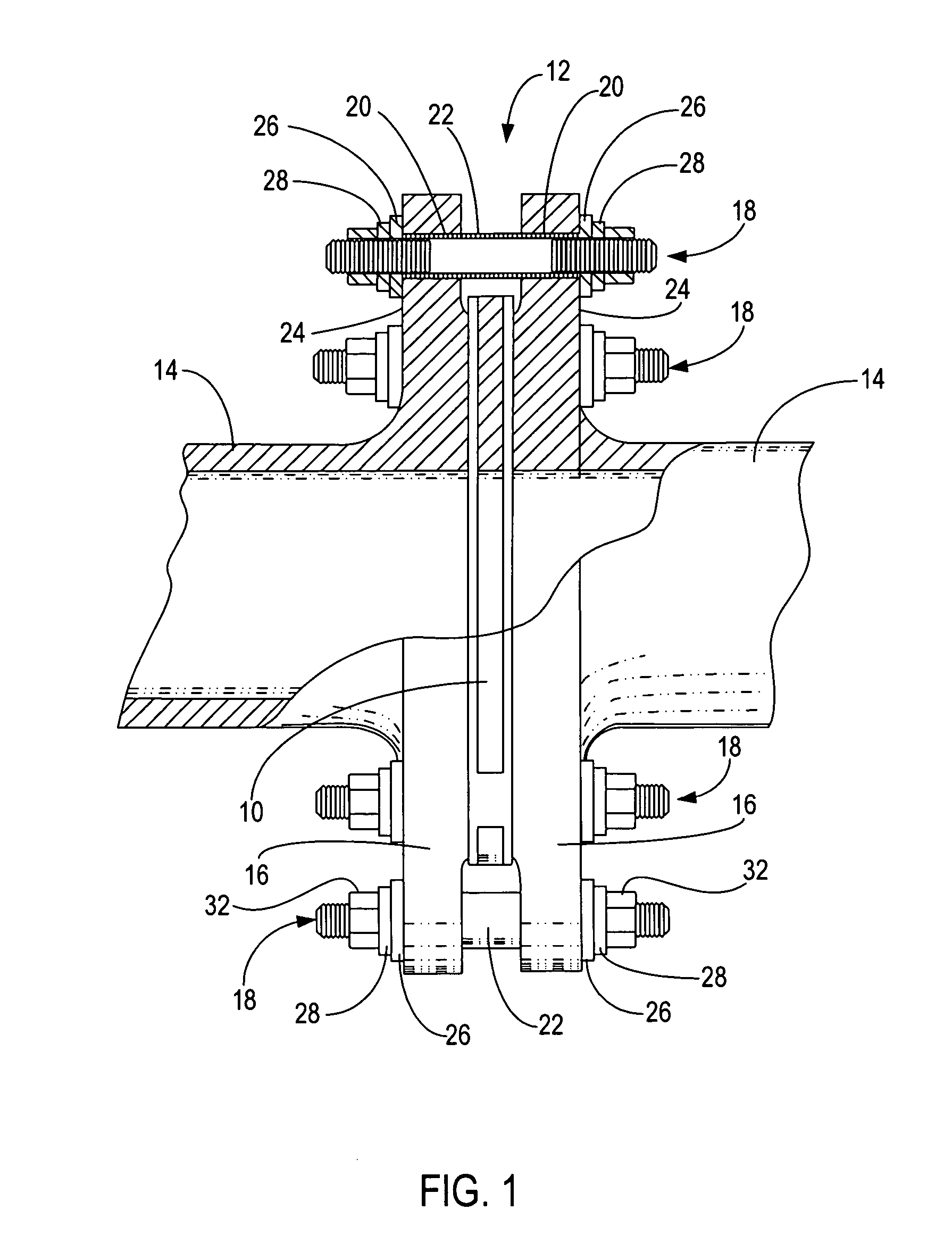
[0030] The present invention is generally directed to an isolation gasket adapted to be used between two flanges in a flow line application. Such flanges may be the flange connection between two sections of pipeline which are connected in end-to-end relation. Alternatively, s...


PUM


Abstract

An isolation gasket for use between joined pieces in a flow line includes, for example, a flat annular metal plate having an opening formed therethrough with a sheet of dielectric material laminated to its opposing side surfaces and a groove formed on the opposing side surfaces which penetrates through the dielectric material and into the metal plate. Each groove extends completely around the opening in the gasket, and a layer of insulating material, as well as a seal element, is disposed in each of the grooves. An isolation system between joined flange pieces utilizes the isolation gasket in combination, for example, with an insulating sleeve receivable in an aligned bore of each of the joined flange pieces, an elongate metal fastener receivable in the insulating sleeve for connecting the joined flange pieces with the isolation gasket therebetween. A flat metal washer with a sheet of dielectric material laminated to one of its opposing side surfaces is receivable on the elongate metal fastener with the laminated dielectric material abutting one of the flange piece outer faces, and at least one metal spring force exerting component is also receivable on the fastener abutting the flat metal washer.

Description

PRIORITY APPLICATION [0001] This application claims the benefit of U.S. Provisional Application No. 60 / 594,396 filed Apr. 4, 2005, entitled “Isolation Gasket, System and Method of Manufacture” incorporated herein by this reference.FIELD OF THE INVENTION [0002] The present invention relates generally to an isolation gasket which is adapted to be interposed and compressed between joined pieces of pipe in a flow line that is operative for fluid flow therethrough without leakage. More particularly, the present invention is directed to an isolation gasket that is part of a seal system which is particularly useful in high pressure, high temperature and / or highly corrosive environments. The present seal device is specifically adapted to provide electrical isolation between joined pipe sections. BACKGROUND OF THE INVENTION [0003] Seal systems using gasket devices have been used in a variety applications to prevent fluid from leaking between joined pieces. For example, a seal device is inter...

Claims


Application Information

Patent Timeline
IPC IPC(8): F16L5/02
CPCF16J15/064F16J15/065F16L25/026F16L23/18F16J15/122
Inventor ANDERSON, THORNTON J.WALLACE, THOMAS
Owner CORROSION CONTROL CORP PIKOTEK
Why Eureka
Try Eureka