

Spark plug having ground electrode protruding member with inner and outer edges
a technology of protruding members and spark plugs, which is applied in the direction of spark plugs, sparking plugs, basic electric elements, etc., can solve the problems of easy hiccup of flame kernel growth, and achieve the effect of ensuring both the durability of the protruding member and the ignition capability of the spark plug, long service life and high reliability of the spark plug
- Summary
- Abstract
- Description
- Claims
- Application Information
AI Technical Summary
Benefits of technology
Problems solved by technology
Method used
Image

Examples
first embodiment
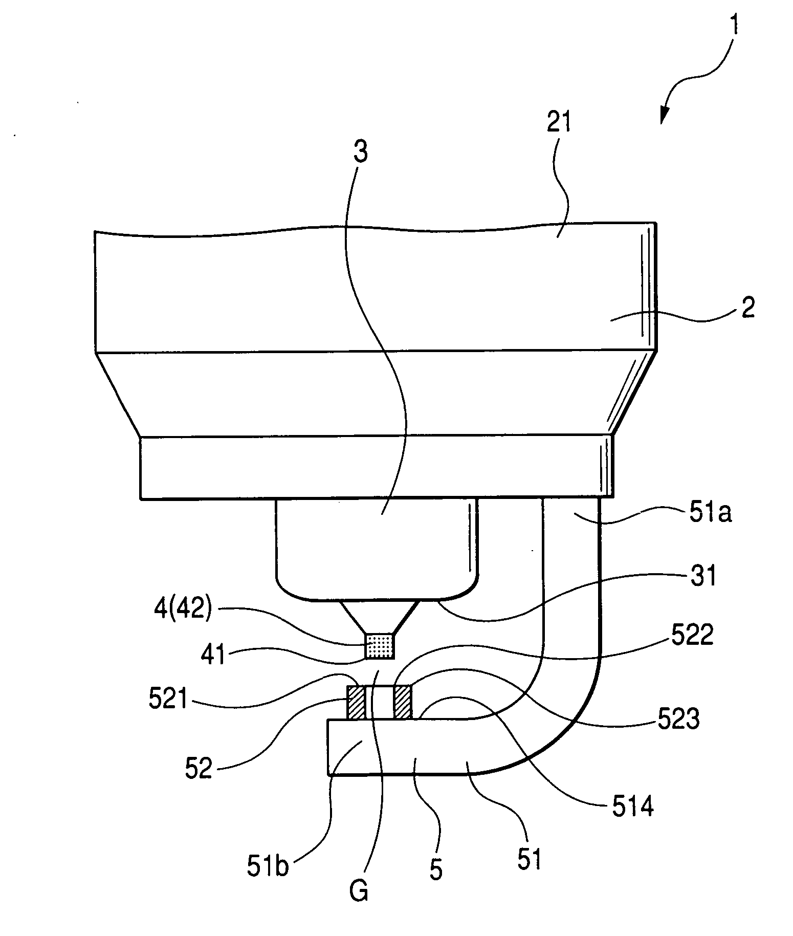
[0062]FIG. 1 shows the overall structure of a spark plug 1 according to the first embodiment of the invention.
[0063] The spark plug 1 is designed for use in an internal combustion engine of an automotive vehicle or a cogeneration system. More specifically, the spark plug 1 is designed to ignite the air-fuel mixture within a combustion chamber of the engine.
[0064] As shown in FIG. 1, the spark plug 1 includes a tubular metal shell 2, an insulator 3, a center electrode 4, and a ground electrode 5.
[0065] The tubular metal shell 2 has a male threaded portion 21 on an outer periphery thereof, through which the spark plug 1 is to be installed in the combustion chamber of the engine. The metal shell 2 is made of a conductive metal material, such as low-carbon steel.
[0066] The insulator 3 is retained in the metal shell 2 such that an end portion 31 thereof protrudes from the metal shell 2. The insulator 3 is made of a ceramic material, such as alumina (Al2O3).
[0067] The center electrod...
experiment 1
[0109] This experiment was conducted to confirm the effect of the present invention on discharge voltage reduction.
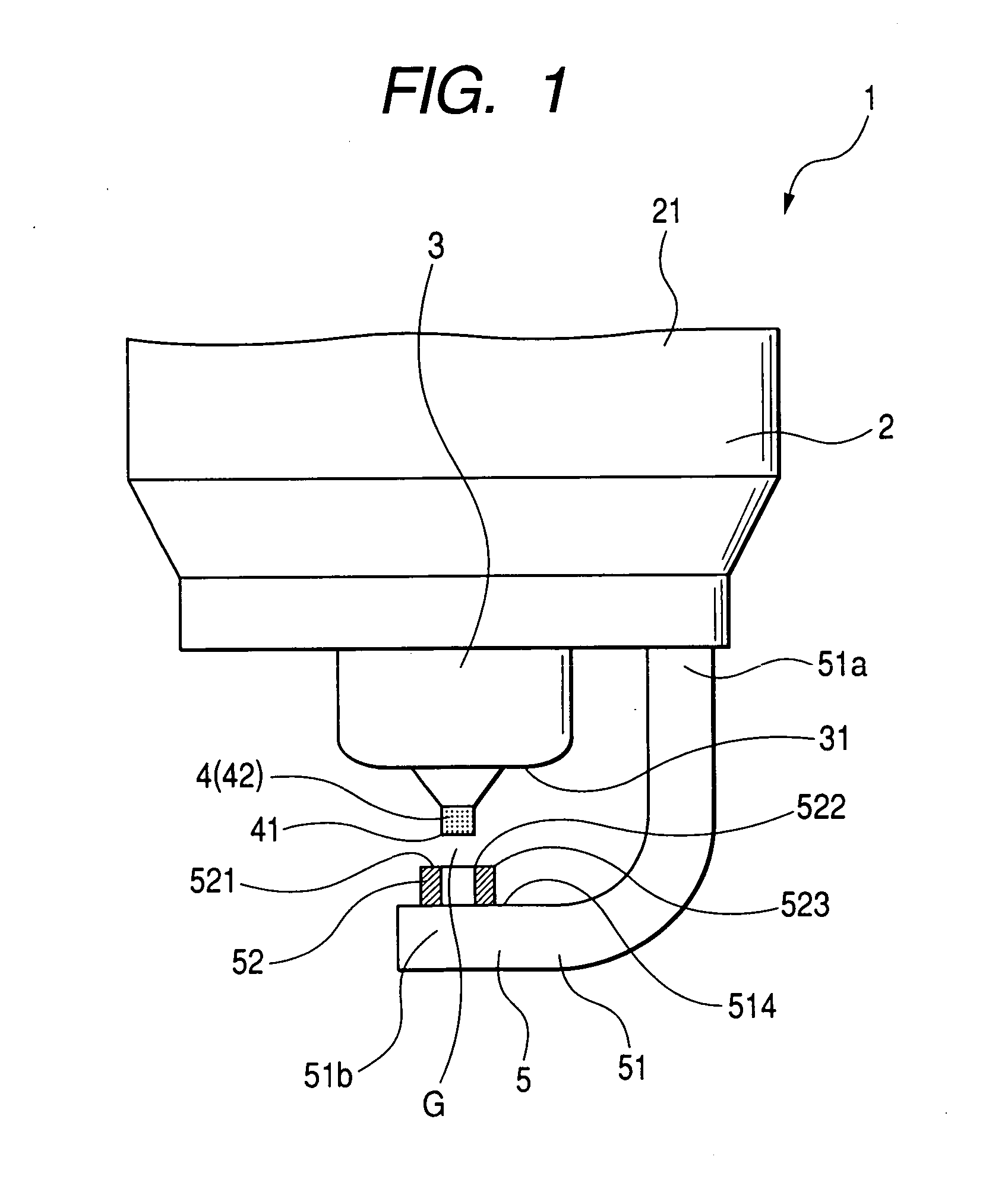
[0110] In the experiment, sample spark plugs, which had the same structure as the spark plug 1 but various |B1−B2| and C, were tested in an atmosphere of 0.6 MPa to measure the discharge voltages Vr1 thereof. In addition, in each of those sample spark plugs, A was 0.5 mm and D was 0.8 mm.
[0111] Further, for the purpose of comparison, another sample spark plug, which had the same structure as the conventional spark plug 9 shown in FIG. 18, was also tested in the atmosphere of 0.6 MPa to measure the discharge voltage Vr2 thereof. In addition, in the sample spark plug, the solid-rod-shaped protruding member had an outer diameter of 0.5 mm and a protruding height of 0.8 mm.
[0112]FIG. 14 shows the test results, where the horizontal axis represents |B1−B2|, while the vertical one represents relative discharge voltage Vr1 / Vr2. Further, in FIG. 14, the plots of “□” indicate ...
experiment 2
[0115] This experiment was conducted to determine the effect of D on the ignition capability of the spark plug 1.
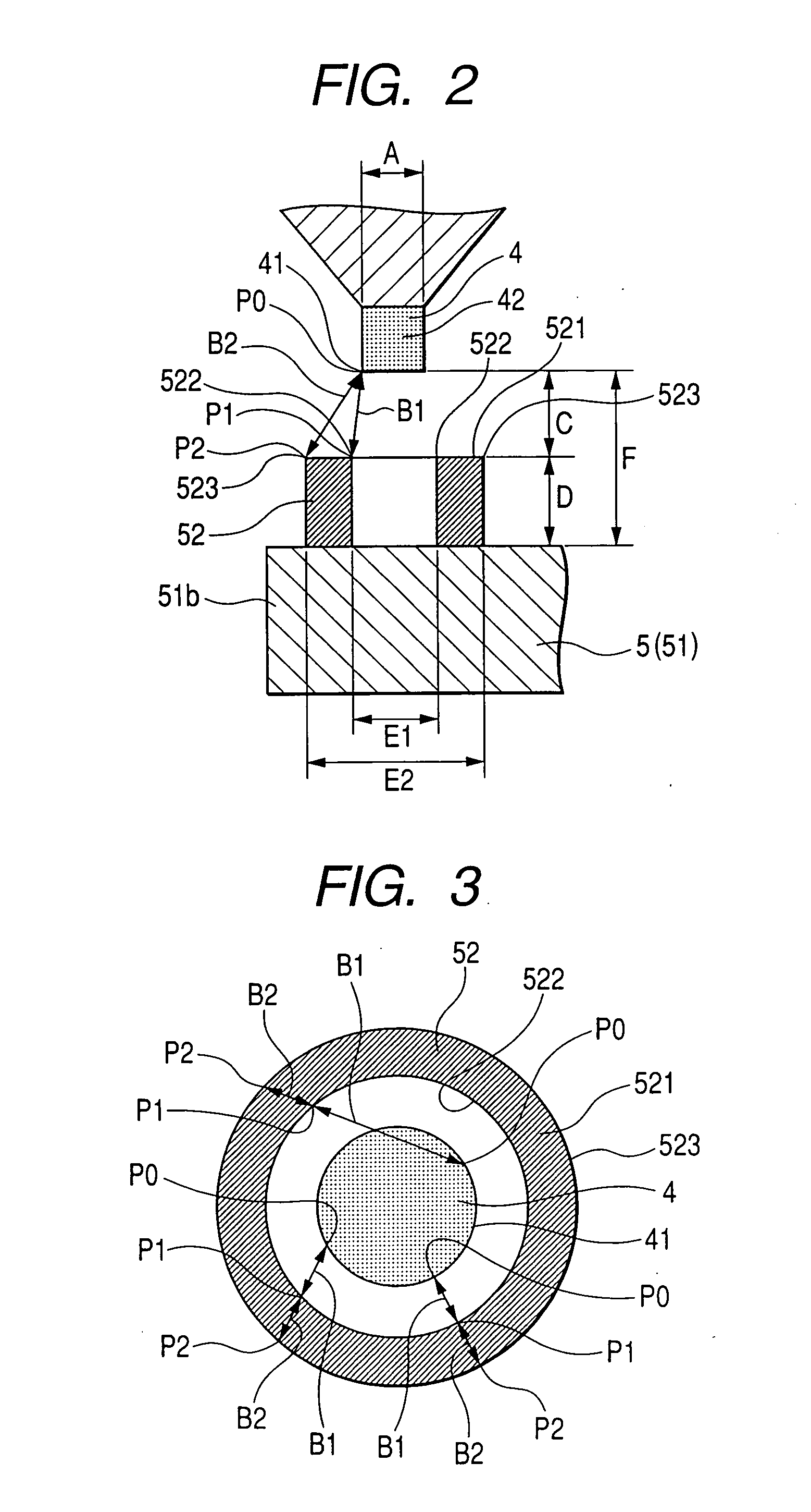
[0116] Sample spark plugs were fabricated which had the same structure as the spark plug 1 but various D. In addition, in each of those sample spark plugs, A was 0.55 mm, C was 0.9 mm, E1 was 0.9 mm, E2 was 1.3 mm, B1 was 0.98 mm, B2 was 0.91 mm, and |B1−B2| was 0.07 mm.
[0117] Further, sample spark plugs having the same structure as the conventional spark plug 9 shown in FIG. 18 were also fabricated for the purpose of comparison. In each of those sample spark plugs, the solid-rod-shaped protruding member had an outer diameter of 0.9 mm.
[0118] All the sample spark plugs were tested, using an automotive engine that had a displacement of 1.8 L and four in-line cylinders, at an engine rotational speed of 800 rpm. The ignition capabilities of the sample spark plugs were evaluated in terms of lean limit air / fuel ratio.
[0119]FIG. 15 shows the test results, where the plots of...
PUM
 Abstract
Description
Claims
Application Information