High frequency power source control circuit and protective circuit apparatus

a power source control circuit and protection circuit technology, applied in the field of back, can solve the problems of increasing the cost and burden of eliminating electromagnetic interference, the cost of multiple inverters is higher than that of single electronic ballast or single inverter, and the quality of lcd monitors, lcd television or lcd advertising apparatuses can be greatly enhanced, and enhance the emitting quality of ccfl tubes or eefl tubes, so as to enhance the stability of the supplied voltage or curren

Inactive Publication Date: 2006-10-05
LU CHAO CHENG
View PDF2 Cites 79 Cited by
  • Summary
  • Abstract
  • Description
  • Claims
  • Application Information

AI Technical Summary

Benefits of technology

[0025] 8. Each of the CCFL tubes or EEFL tubes can get the set tube current compensation, so the quality of the LCD monitor, LCD television or LCD advertising apparatus can be greatly enhanced.
[0026] 9. Using the PWM precision voltage stabilizing circuit and the PWM precision circuit stabilizing circuit can enhance the emitting quality of the CCFL tubes or EEFL tubes and the stability of the supplied voltage or current to the CCFL tubes or EEFL tubes.

Problems solved by technology

Because there are some differences between the high working frequencies of the inverters, many interference frequencies are generated in the LCD monitor, and the cost and burden for eliminating the electromagnetic interference are thus increased.
The cost of multiple inverters is higher than that of single electronic ballast or a single inverter.

Method used


Image

  • High frequency power source control circuit and protective circuit apparatus
  • High frequency power source control circuit and protective circuit apparatus
  • High frequency power source control circuit and protective circuit apparatus

Examples


second embodiment

[0052]FIG. 6 shows CCFL or EEFL tube current control circuits according to the invention. As shown in FIG. 5, two CCFL or EEFL tube current control circuits are provided. Multiple CCFL or EEFL tube current control circuits may be added in FIG. 6 in order to increase the control range of the CCFL or EEFL tube current. In FIG. 6, the bridge rectifier DGA to the bridge rectifier DGN represent that multiple bridge rectifiers are used. The bridge rectifier DGA, the photocoupler PhA and the comparator AA constitute one set, while the bridge rectifier DGN, the photocoupler PhN and the comparator AN constitute another set. The bridge rectifiers DG2, DGA, DGN and DG3 are connected in series, and the breakdown voltage of the output side of the photo coupler is determined according to the requirements. The operation principle of FIG. 6 is the same as that of FIG. 5.

third embodiment

[0053]FIG. 7 shows CCFL or EEFL tube current control circuits according to the invention. As shown in FIG. 5, two CCFL or EEFL tube current control circuits are provided. Multiple output sides of photocouplers can be connected in series in FIG. 7 in order to increase the breakdown voltage of the photocoupler, wherein DGR means that multiple photocouplers are used. For example, if the breakdown voltage for each set is desired to be 250V, two photocouplers with the breakdown voltages of 100V and one photocoupler with the breakdown voltage of 50V may be connected in series. The number of serially connected photocouplers and the number of the control circuits can be determined according to the requirement. The function of the high frequency filter condenser CF is to make the positive and negative DC terminals of the bridge rectifier output the DC voltage, and is the same as that of the high frequency filter condenser CF of FIG. 6.

[0054]FIG. 8 shows a PWM and high frequency power output ...


PUM


Abstract

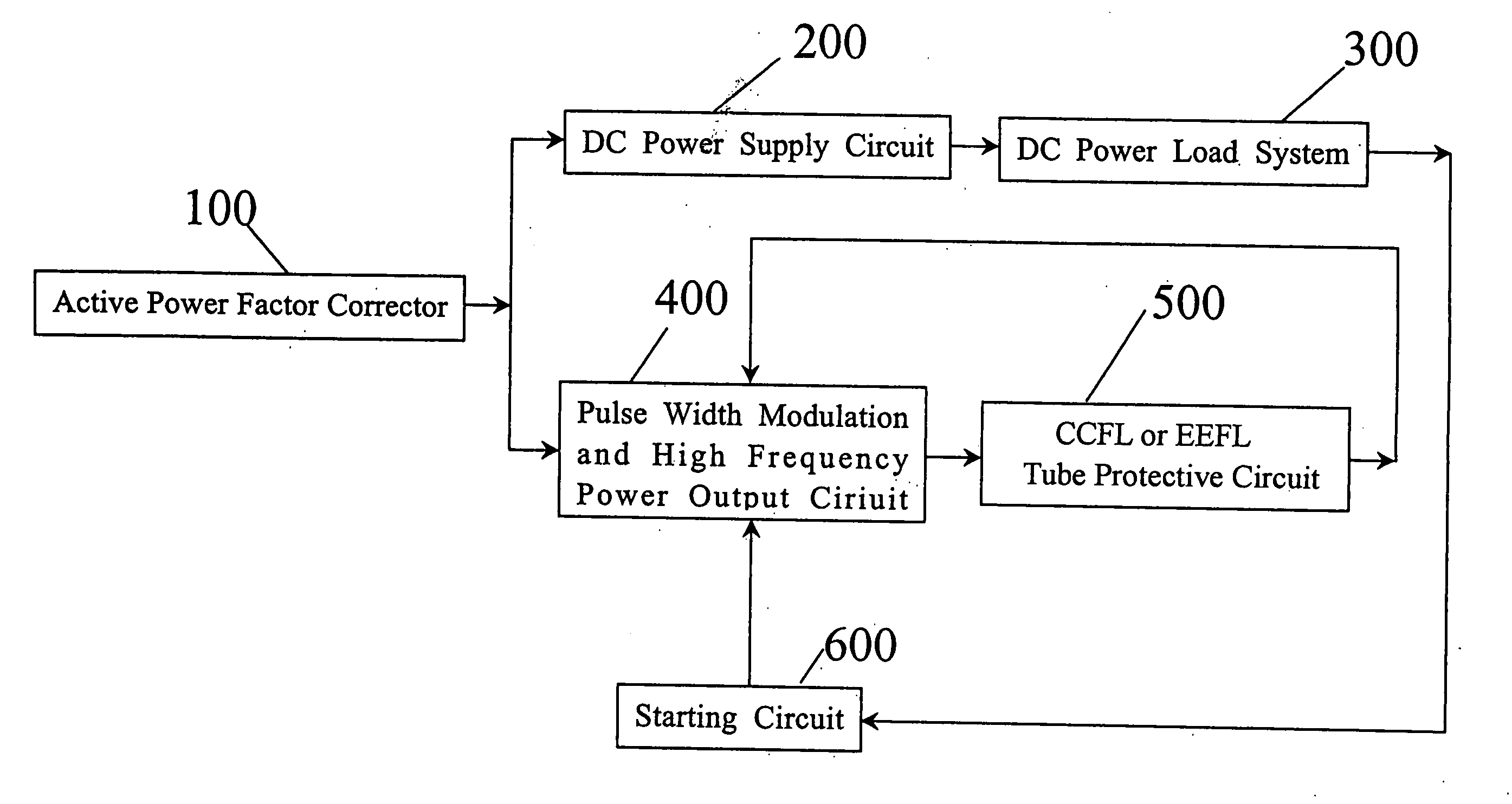
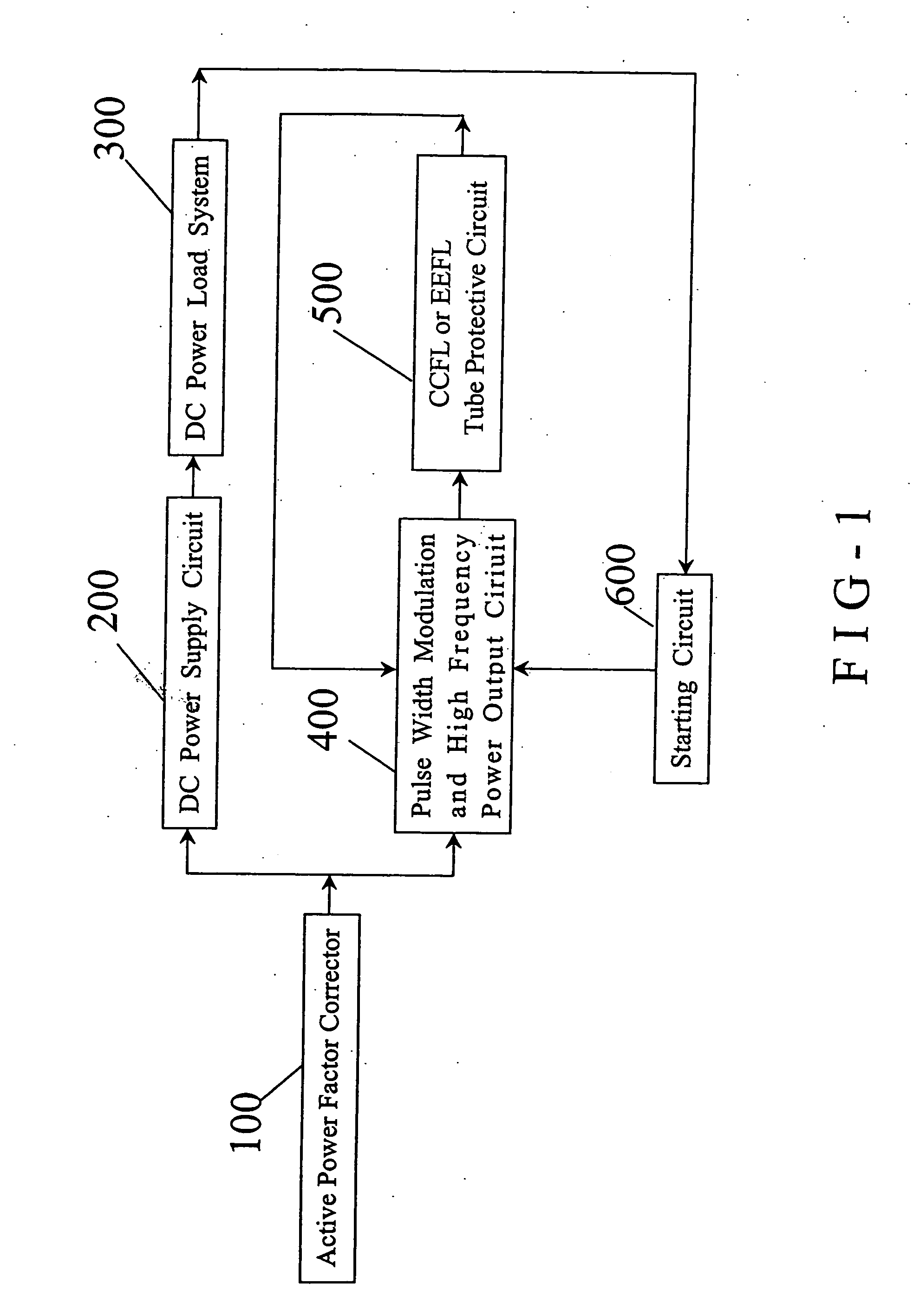
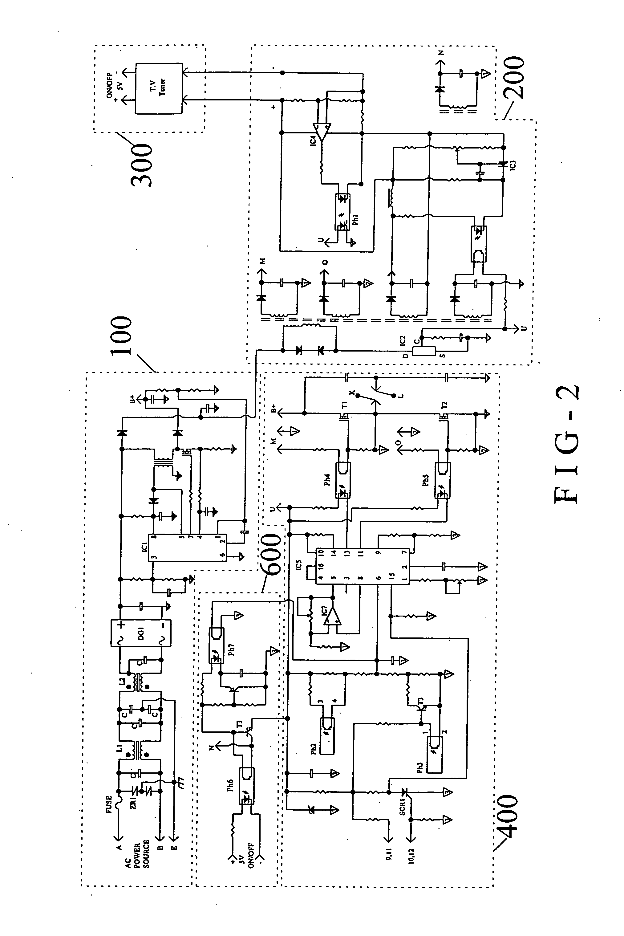
A precision voltage control circuit applicable to a PWM (Pulse Width Modulation) circuit can offer CCFL (Cold Cathode Fluorescent Lamp) or EEFL (External Electrode Fluorescent Lamp) tubes a stable high frequency voltage or current, so that each CCFL or EEFL tube can get an appropriate compensation current and an optimal emitting efficiency and enhance its emitting quality. The circuit also has an overload current, low current, and overload voltage and low voltage protective circuit to protect the CCFL or EEFL tubes from being injured. The circuit can also be applied to the TFT LCD TV or other large LCD panels, and develops the best display effect of each LCD tube.

Description

BACKGROUND OF THE INVENTION [0001] 1. Field of the Invention [0002] The invention is applicable to a backlight source device of a large or ultra-large LCD monitor, which needs multiple CCFLs (Cold Cathode Fluorescent Lamps) or EEFLs connected in parallel as a light source. The required high frequency power is supplied from electronic ballast or a switching power in order to protect the CCFL tubes or EEFL tubes with a single working frequency, a stable circuit, a high emitting efficiency, a high quality, and a small distortion. The invention provides a measurement and protective circuits and precise and stable voltage and current for PWM (Pulse Width Modulation) in order to supply the power to a TFT LCD TV system. [0003] 2. Description of the Related Art [0004] When the conventional CCFLs or EEFLs are used in a backlight source for a LCD monitor, an inverter typically lights one or two CCFLs or EEFLs. When the conventional CCFLs or EEFLs are used in a large LCD monitor or a large tel...

Claims


Application Information

Patent Timeline
Patent Type & Authority Applications(United States)
IPC IPC(8): H05B37/02H05B41/36
CPCH05B41/2813Y02B20/22H05B41/285Y02B20/00
Inventor LU, CHAO-CHENG
Owner LU CHAO CHENG
Why Eureka
Try Eureka