Liquid crystal display

Active Publication Date: 2006-10-05
PANASONIC LIQUID CRYSTAL DISPLAY CO LTD +1
View PDF10 Cites 30 Cited by
  • Summary
  • Abstract
  • Description
  • Claims
  • Application Information

AI Technical Summary

Benefits of technology

[0013] The present invention has been made to solve the above-described issue and aims to provide

Problems solved by technology

However, if liquid crystal molecules are tilted omnidirectionally, a black line called a domain is observed in a cross-nicol state in the area where liquid crystal molecules are tilted along a direction parallel to an absorption axis of each polarization plate and light cannot be transmitted.
This may cause a lowered transmittance.
However, with the liquid crystal display in the VA mode

Method used


Image

  • Liquid crystal display
  • Liquid crystal display
  • Liquid crystal display

Examples


Example

First Embodiment

[0041] This embodiment is effective for improving a contrast ratio, of a liquid crystal display in a VA mode adopting a circular polarization plate, in a wide viewing angle range, by using as a protective layer of the polarization plate a film having generally isotropical optical characteristics along an omnidirection, in place of a TAC film.

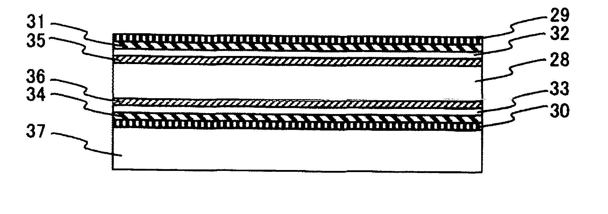
[0042]FIG. 1 is a schematic diagram showing the cross sectional structure of a liquid crystal display according to the invention.

[0043] The liquid crystal display of the invention is constituted of a liquid crystal cell 28 disposed between a first polarization plate 29 and a second polarization plate 30. Three retardation films are disposed between the first polarization plate 29 and the liquid crystal cell 28. These three retardation films are a first retardation film 31, a second retardation film 32 and a first negative C-Plate 35 in this order from the first polarization plate 29 side. Similarly, three retardation films are...

Example

Second Embodiment

[0089] Next, the second embodiment will be described with reference to the accompanying drawings. A transflective liquid crystal display can be realized by applying a circular polarization plate to a liquid crystal display in the VA mode. The layout of polarization plates and retardation films of a transflective liquid crystal display in the VA mode of the second embodiment is similar to that of the first embodiment, and the advantages similar to those of the first embodiment can be obtained.

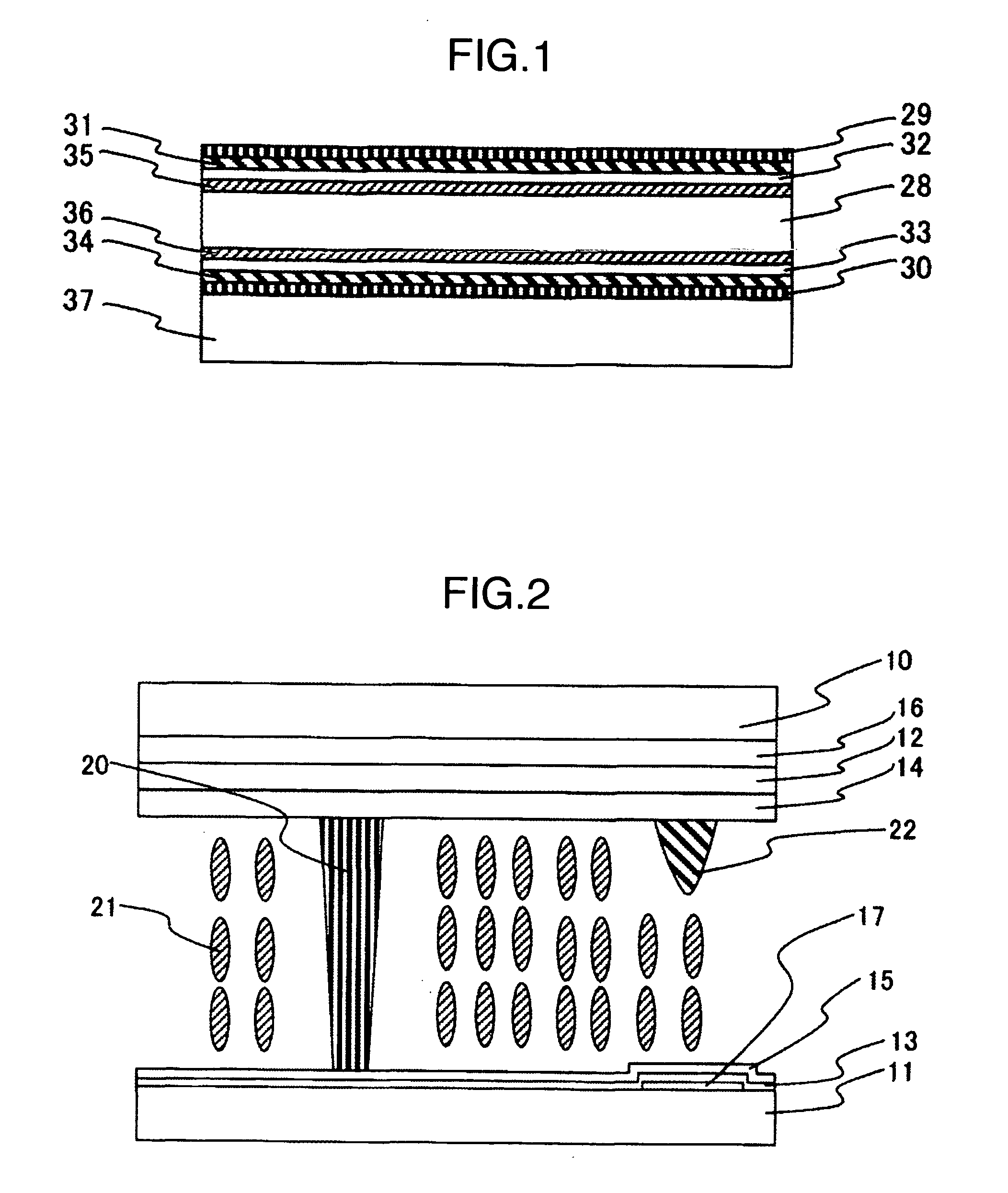
[0090]FIG. 12 is a schematic diagram showing the cross sectional structure of a liquid crystal cell 28 of the transflective liquid crystal display in the VA mode, taken along line B-B′ shown in FIG. 13. The transflective liquid crystal display of the second embodiment has a transmission area (T area in FIG. 12) and a reflection area (R area in FIG. 12) in one pixel. The liquid crystal cell 28 has a first substrate 10, a liquid crystal layer 21 and a second substrate 11, and th...

Example

Third Embodiment

[0095] Next, the third embodiment will be described with reference to the accompanying drawings. In the third embodiment, a positive C-Plate for compensating for a phase difference of a TAC film is disposed between a negative C-Plate and the TAC film to thereby obtain advantages similar to those when the phase difference of the protective layer is set to 0.

[0096]FIG. 14 is a schematic diagram showing the cross sectional structure of a liquid crystal display according to the third embodiment. The liquid crystal display of this embodiment is constituted of a liquid crystal cell 28 disposed between a first polarization plate 29 and a second polarization plate 30. Four retardation films are disposed between the first polarization plate 29 and liquid crystal cell 28. The four retardation films include a first positive C-Plate (hereinafter called a positive C-Plate) 44, a first retardation film 31, a second retardation film 32 and a first negative C-Plate 35 in this orde...


PUM


Abstract

A liquid crystal display of a vertical alignment (VA) mode using a circular polarization plate is provided which can reduce light leak as observed along an oblique direction and achieve a high contrast ratio. The VA mode uses a liquid crystal layer of vertical alignment in an initial alignment state. A film having generally isotropic optical characteristics in an omnidirection is used as a protective film, on a liquid crystal cell side, of first and second polarization plates disposed outside the liquid crystal cell, and first and fourth retardation films have an Nz coefficient smaller than 1.

Description

BACKGROUND OF THE INVENTION [0001] 1 Field of the Invention [0002] The present invention relates to a liquid crystal display for displaying images. [0003] 2. Description of the Related Art [0004] A liquid crystal display is a non-emission type display for displaying images by adjusting an optical transmission amount and has characteristics of thinness, light weight and low consumption power. [0005] Liquid crystal displays include a transmission type liquid crystal display and a reflection type liquid crystal display. In the transmission type liquid crystal display, a light source (hereinafter called a backlight) is disposed at the back of the display and an optical transmission amount of the backlight is adjusted to display images. In the reflection type liquid crystal display, external light such as room illumination and sun light is made incident upon the display from the front side and the optical reflection amount of the external light is adjusted to display images. There is a l...

Claims


Application Information

Patent Timeline
IPC IPC(8): G02F1/1335
CPCG02F1/133528G02F1/133634G02F2413/13G02F2201/50G02F2001/133742G02F1/133742G02F1/1335
Inventor OKA, SHINICHIROADACHI, MASAYAKOMURA, SHINICHIHIYAMA, IKUO
Owner PANASONIC LIQUID CRYSTAL DISPLAY CO LTD
Why Eureka
Try Eureka