Erasing non-volatile memory utilizing changing word line conditions to compensate for slower erasing memory cells

a non-volatile memory and word line condition technology, applied in static storage, digital storage, instruments, etc., can solve the problems of increasing program and erase times, over-erasure of faster erasing memory cells, and shortening the cycling life of memory cells or nand strings, so as to achieve efficient and consistent erasing of memory cells

Active Publication Date: 2006-10-05
SANDISK TECH LLC
View PDF66 Cites 62 Cited by
  • Summary
  • Abstract
  • Description
  • Claims
  • Application Information

AI Technical Summary

Benefits of technology

[0022] The present invention, roughly described, pertains to technology for erasing memory devices in a manner that provides a more efficient and consistent erasure of memory cells. In accord

Problems solved by technology

This can lead to over-erasure of faster erasing memory cells because they will continue to be subjected to erase voltages that are applied to sufficiently erase the slower memory cells of the NAND string.
Thus, the different erase r

Method used


Image

  • Erasing non-volatile memory utilizing changing word line conditions to compensate for slower erasing memory cells
  • Erasing non-volatile memory utilizing changing word line conditions to compensate for slower erasing memory cells
  • Erasing non-volatile memory utilizing changing word line conditions to compensate for slower erasing memory cells

Examples


Embodiment Construction

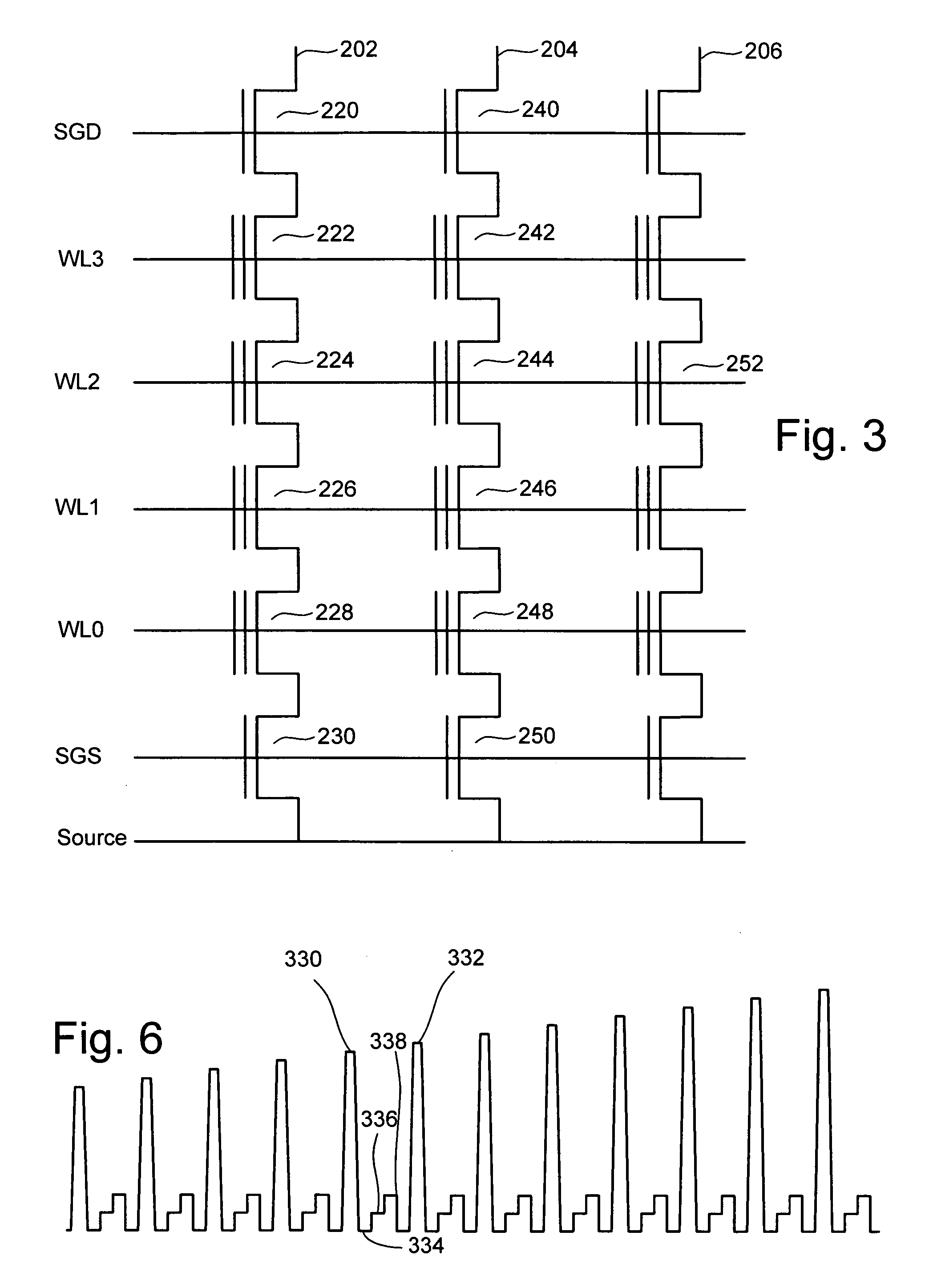
[0053]FIG. 4 is a block diagram of one embodiment of a flash memory system that can be used to implement the present invention. Other systems and implementations can be used. Memory cell array 302 is controlled by column control circuit 304, row control circuit 306, c-source control circuit 310 and p-well control circuit 308. Column control circuit 304 is connected to the bit lines of memory cell array 302 for reading data stored in the memory cells, for determining a state of the memory cells during a program operation, and for controlling potential levels of the bit lines to promote or inhibit programming and erasing. Row control circuit 306 is connected to the word lines to select one of the word lines, to apply read voltages, to apply program voltages combined with the bit line potential levels controlled by column control circuit 304, and to apply an erase voltage. C-source control circuit 310 controls a common source line (labeled as “C-source” in FIG. 6) connected to the memo...


PUM


Abstract

Voltage conditions applied to the memory cells of a non-volatile memory system are changed during erase operations in order to equalize the erase behavior of the select memory cells with other memory cells of the system that are being concurrently erased. The changed conditions can compensate for capacitively coupled voltages within a NAND string. After biasing a NAND string for an erase operation and beginning application of the erase voltage pulse, the word lines of one or more interior memory cells can be floated. By floating the selected interior word lines, the peak erase potential created across the tunnel dielectric region of the cells coupled thereto is decreased from its normal level. Consequently, the erase rates of these cells are slowed to substantially match that of the slower erasing end memory cells of the string. Different word lines can be floated at different times to alter the erase behavior of different memory cells by different amounts.

Description

PRIORITY CLAIM [0001] The present application claims priority from U.S. Provisional Patent Application No. 60 / 667,043, entitled “NON-VOLATILE MEMORY ERASE OPERATIONS WITH OVER-ERASE PROTECTION,” by Hemink et al., filed Mar. 31, 2005, incorporated by reference herein in its entirety. CROSS-REFERENCE TO RELATED APPLICATIONS [0002] The following applications are cross-referenced and incorporated by reference herein in their entirety: [0003] U.S. patent application Ser. No. ______ (Attorney Docket No. SAND-01054US2), entitled, “SYSTEMS FOR ERASING NON-VOLATILE MEMORY UTILIZING CHANGING WORD LINE CONDITIONS TO COMPENSATE FOR SLOWER ERASING MEMORY CELLS,” by Masaaki Higashitani, filed concurrently; [0004] U.S. patent application Ser. No. 11 / 025,620, entitled, “WORD LINE COMPENSATION IN NON-VOLATILE MEMORY ERASE OPERATIONS,” by Wan et al., filed Dec. 29, 2004; [0005] U.S. patent application Ser. No. ______ (Attorney Docket No. SAND-01066US0), entitled, “ERASING NON-VOLATILE MEMORY USING IN...

Claims


Application Information

Patent Timeline
IPC IPC(8): G11C16/04
CPCG11C11/5628G11C11/5635G11C16/0483G11C16/12G11C16/16G11C16/3404G11C2216/18G11C16/345G11C16/3454G11C16/3468G11C16/3472G11C16/3477G11C2211/5621G11C16/3409
Inventor HIGASHITANI, MASAAKI
Owner SANDISK TECH LLC
Why Eureka
Try Eureka