Computed tomography system with adjustable focal spot-to-detector distance

a computed tomography and focal spot technology, applied in tomography, instruments, applications, etc., can solve the problems of reducing the accessibility of the patient during the scan process, affecting the imaging quality of the system, and affecting the scanning comfort of the patient, so as to improve the accessibility, reduce the dependence of image quality on the dimension of the subject to be scanned, and increase the diameter of the patient opening.

Inactive Publication Date: 2006-10-05
SIEMENS HEALTHCARE GMBH
View PDF3 Cites 22 Cited by
  • Summary
  • Abstract
  • Description
  • Claims
  • Application Information

AI Technical Summary

Benefits of technology

[0015] 3. with increased diameter of the patient opening, a subject to be scanned with a larger volume can be inserted into the gantry for scanning or a better accessibility to a subject to be scanned can be achieved.
[0016] An adjustment of the distance between the focal spot and the detector on the basis of the dimension of a subject to be scanned is thus realized in real time by the present invention; the dependency of the image quality on the dimension of a subject to be scanned is reduced, whereby the clinical application range of the CT system is significantly expanded and a patient opening that can be expanded similar to the diaphragm of a camera is simultaneously provided by the invention.

Problems solved by technology

Not only does the accessibility to the patient during the scan process thereby decrease, but this can also lead to an impairment of the imaging quality of the system due to differences between volumes of patients (body parts) to be scanned, or differences in the quantities of the emitted / received x-rays.
Since the aperture angle of the x-ray fan emitted by the focal spot of the x-ray tube and the distance between the focal spot and the detector are fixed, the scanning of the patient within the patient opening is very uncomfortable when the volume of a patient to be scanned is extremely large, and the x-rays possibly do not entirely cover the volume of the patient in the FOV—field of view.
If an x-ray tube with a larger aperture angle of the fan beam is used in order to overcome the such problems above, the cost of the apparatus rises significantly.
Designing a computed tomography system with an adjustable focal spot-to-detector distance is therefore a problem needing a solution in this field.

Method used


Image

  • Computed tomography system with adjustable focal spot-to-detector distance
  • Computed tomography system with adjustable focal spot-to-detector distance

Examples


Embodiment Construction

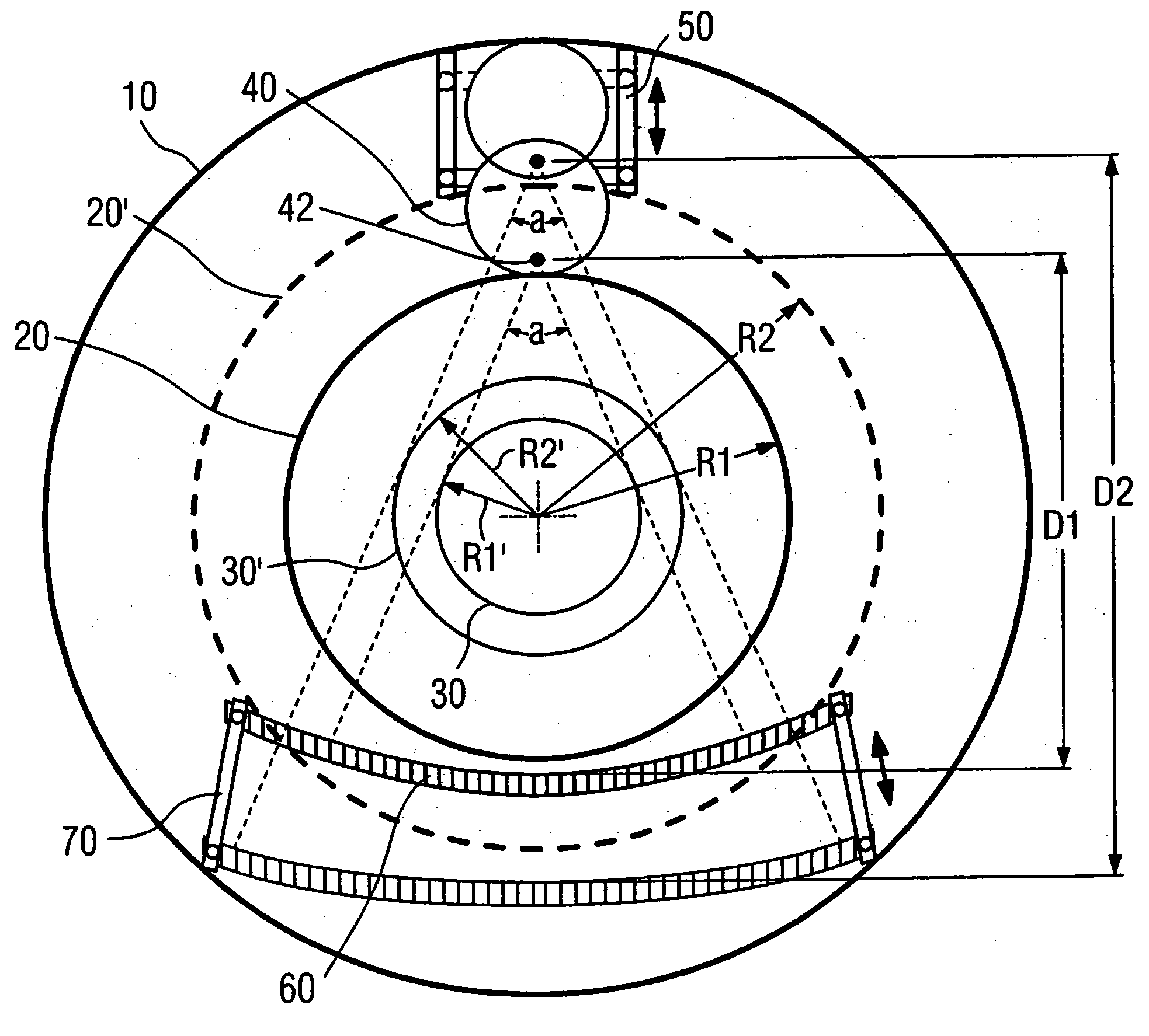
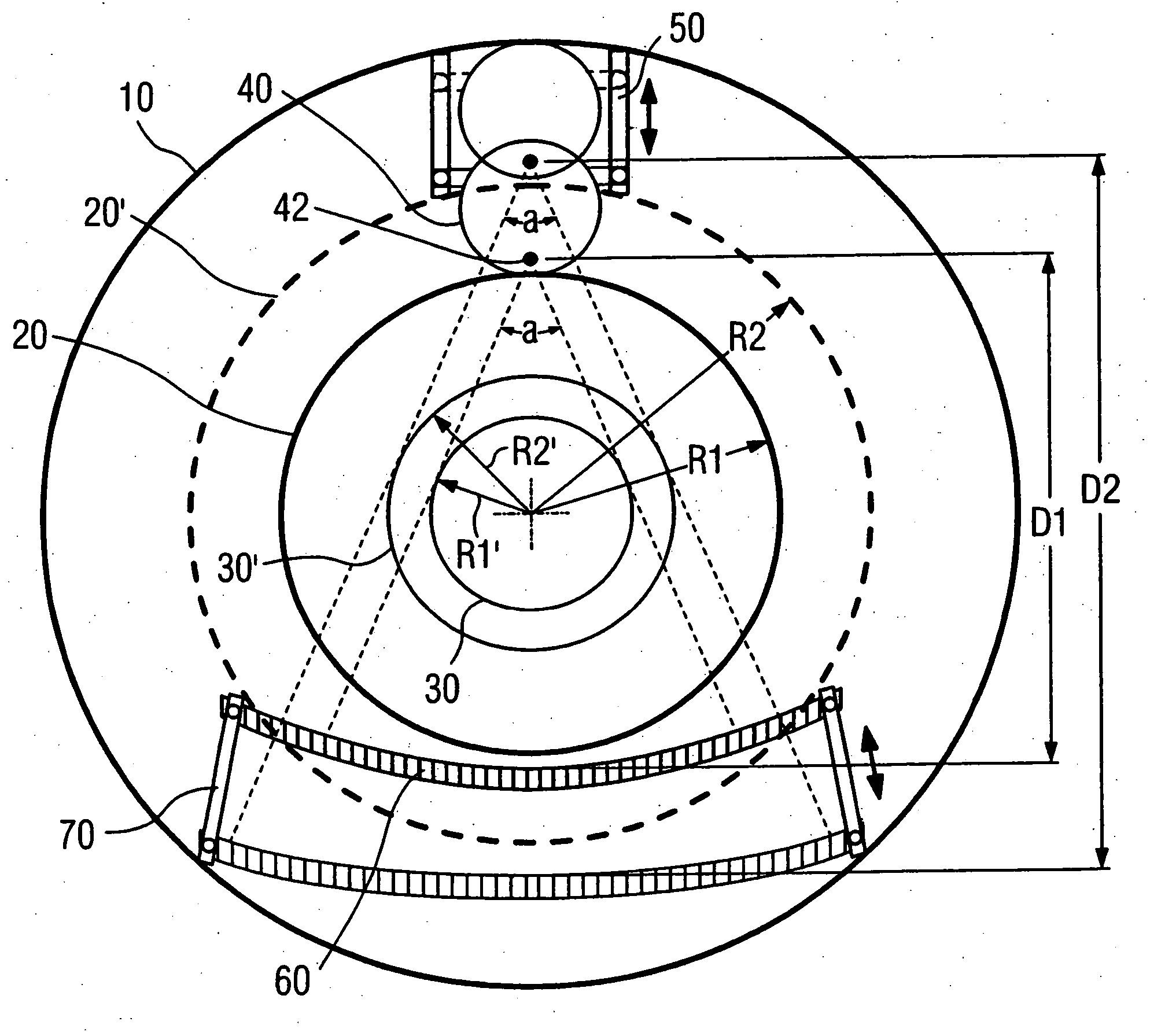
[0018] As shown in the FIGURE, the gantry 10 of the CT system has a patient opening 20, allowing a patient to be scanned to be introduced into the gantry 10 through the patient opening 20 with a radius of R1. An x-ray tube 40 is installed on one side of the gantry 10 and has a focal spot 42. The x-ray fan beam emitted by the focal spot 42 has a fixed aperture angle a. A detector mount 60 is installed on the other side of the gantry 10 opposite the x-ray tube 40. A detector for reception of x-rays emitted by the focal spot 42 is disposed on the detector mount 60. The distance between the focal spot 42 of the x-ray tube 40 and of the detector mount 60 is D1. Dependent on the fixed aperture angle a of the x-ray fan beam emitted by the focal spot 42 and the distance D1, the scan area 30 of the x-ray tube 40 in the patient opening 20 exhibits a radius of R1′.

[0019] So that the distance between the focal spot 42 of the x-ray tube 40 and the patient can be flexibly adjusted according to t...


PUM

PropertyMeasurementUnit
computed tomographyaaaaaaaaaa
aperture angleaaaaaaaaaa
distanceaaaaaaaaaa

Abstract

A computed tomography system with an adjustable focal spot-to-detector distance has a gantry provided with a patient opening, an x-ray tube and a detector, respectively mounted at opposite sides of the gantry. The x-ray tube has a focal spot and the x-ray fan beam radiated from the focal spot exhibits a fixed aperture angle. The x-ray tube is installed on a linear track and can be moved along the rail of the linear track.

Description

BACKGROUND OF THE INVENTION [0001] 1. Field of the Invention [0002] The present invention concerns a computed tomography (CT) system, in particular a computed tomography system with an adjustable focal spot-to-detector distance. [0003] 2. Description of the Prior Art [0004] In a conventional CT system, the aperture angle of the x-ray fan beam radiated by the x-ray tube and the distance between the focal spot of the x-ray tube and its corresponding detector are fixed. Not only does the accessibility to the patient during the scan process thereby decrease, but this can also lead to an impairment of the imaging quality of the system due to differences between volumes of patients (body parts) to be scanned, or differences in the quantities of the emitted / received x-rays. [0005] In a typical CT system, a patient opening is mounted at a gantry in which a patient can be moved for scanning in the gantry. The x-ray tube is mounted on one side of the gantry and the focal spot of the x-ray tub...

Claims


Application Information

Patent Timeline
Patent Type & Authority Applications(United States)
IPC IPC(8): A61B6/00G01N23/00G21K1/12H05G1/60
CPCA61B6/032A61B6/588G01N2223/612G01N2223/419G01N23/046A61B6/4435A61B6/4452
Inventor DU, JIAN
Owner SIEMENS HEALTHCARE GMBH
Why Eureka
Try Eureka