Optical unit and imaging apparatus

an optical unit and imaging technology, applied in the direction of printers, instruments, camera focusing arrangement, etc., can solve the problems of inability to meet the need for reducing the thickness, and the projection area in the optical axis direction is reduced, and achieves small projection area in the optical axis direction, small thickness, and high space efficiency

Inactive Publication Date: 2006-10-05
KONICA MINOLTA OPTO
View PDF2 Cites 3 Cited by
  • Summary
  • Abstract
  • Description
  • Claims
  • Application Information

AI Technical Summary

Benefits of technology

[0019] As described above, since the optical system driving device and the light quantity control driving device are arranged so as to overlap each other in the direction perpendicular to the optical axis, the optical unit or imaging apparatus of the present invention has a small thickness in the optical axis direction. Moreover, both the optical system driving device...

Problems solved by technology

However, the light quantity control driving device and the optical system driving device are obstructive factors in further reducing the projection area in the optical axis direction of the optical unit.
Although the projection area in the optical axis direction i...

Method used


Image

  • Optical unit and imaging apparatus
  • Optical unit and imaging apparatus
  • Optical unit and imaging apparatus

Examples


Embodiment Construction

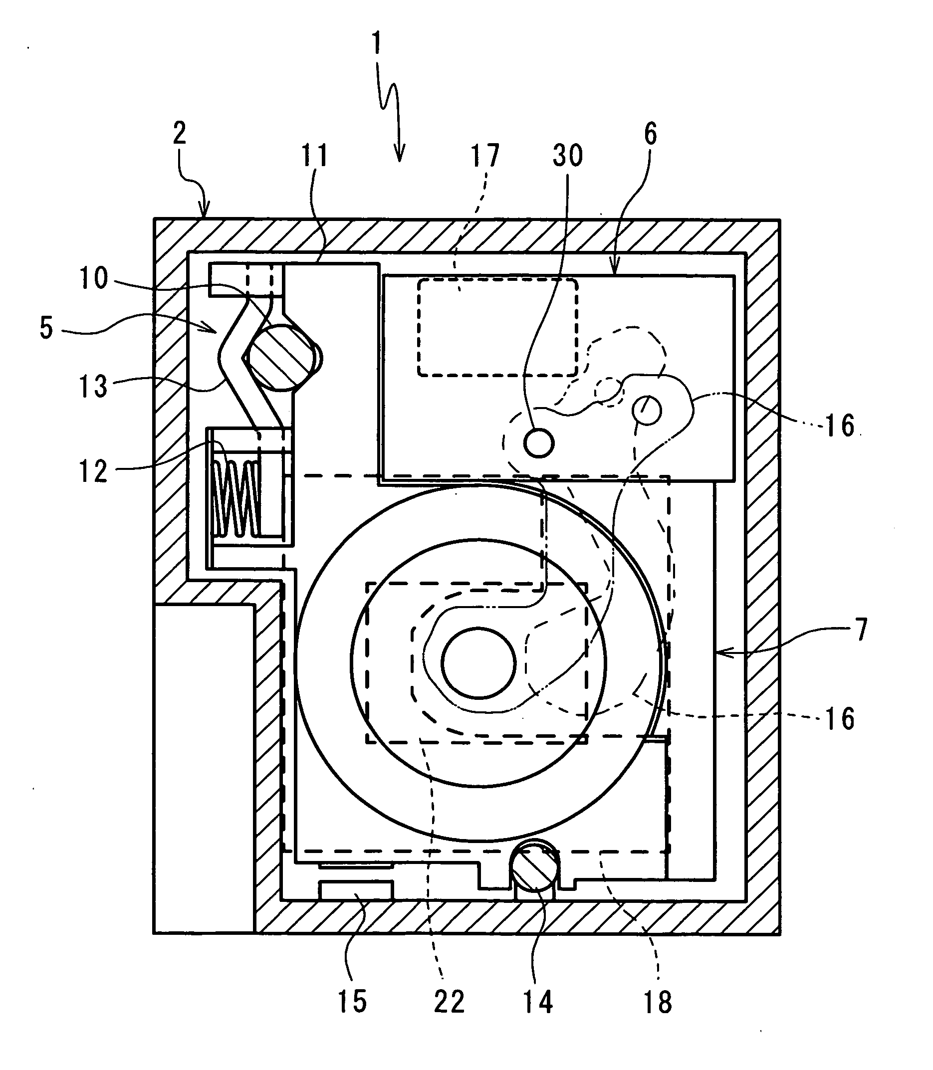
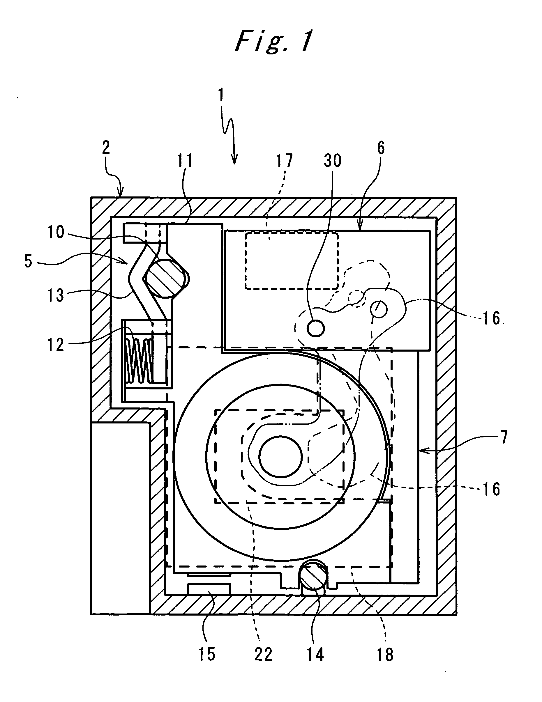
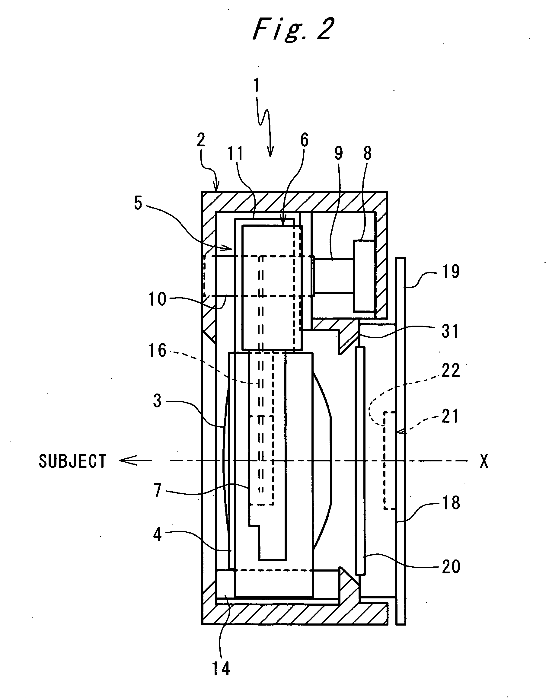
[0023] Referring to FIGS. 1 and 2, a description is made below on an imaging apparatus, according to an embodiment of the present invention.

[0024]FIG. 1 shows a state in which the imaging apparatus of the first embodiment of the present invention is viewed from the direction of the subject (front), and FIG. 2 shows a state in which the imaging apparatus is viewed from a side. The imaging apparatus comprises an imaging device package (imaging device) 18 and an optical unit 1 for projecting an image of a subject on the imaging device 18. The optical unit 1 has a lens frame 4 supporting a lens group (optical system) 3 and supported by a optical system driving device 5 in a housing 2. A shutter unit 7 and a shutter driving device (light quantity control driving device) 6 are fixed to the lens frame 4. The optical system driving device 5 and the shutter driving device 6 are adjacently arranged so as to overlap each other in a view from a direction perpendicular to the optical axis X of ...


PUM


Abstract

Provided is a compact thin type optical unit provided also with a housing 2 having an mounting surface 31 for mounting an imaging device 18 on, an optical system driving device 5 for driving the optical system 3, a light quantity control member 16 for controlling a light quantity projecting on the imaging device 18 and a light quantity control driving device 6 for driving the light quantity control member 16, and the optical system driving device 5, wherein the light quantity control driving device 6 are arranged outside a same side of the mounting surface 31 so as to overlap each other in a direction perpendicular to an optical axis X of the optical system 3.

Description

[0001] This application is based on applications No. 2005-093572 filed in Japan, the contents of which are hereby incorporated by reference. BACKGROUND OF THE INVENTION [0002] The present invention relates to an optical unit and an imaging apparatus which project an image of a subject on an imaging device. [0003] Generally, in an imaging apparatus projecting an image of a subject on an imaging device, a movable optical system (e.g. lens group) is placed in front of (on the subject side of) an imaging device that has a rectangular imaging surface, and a light quantity control member such as a shutter, an aperture diaphragm or the like is provided within or in front of the movable optical system. [0004] A light quantity control driving device as a motor and so on for driving the shutter or the aperture diaphragm and an optical system driving device for moving the movable optical system in 6 the optical axis direction are arranged at an interval of a large angle around the optical axis...

Claims


Application Information

Patent Timeline
IPC IPC(8): G03B13/18G03B9/08
CPCG03B9/10H04N5/2254G03B17/02H04N23/55
Inventor HOSOTA, HIROYOSHIKONISHI, HIROTOSHI
Owner KONICA MINOLTA OPTO
Why Eureka
Try Eureka