Optical transmission apparatus

a transmission apparatus and optical technology, applied in the field of optical transmission apparatus, can solve the problems of degrading the osnr, the requirement for the improvement of the oadm system cannot be met, and the above-oadm system b>1000/b> cannot meet the requirement,

Inactive Publication Date: 2006-10-05
FUJITSU LTD
View PDF7 Cites 14 Cited by
  • Summary
  • Abstract
  • Description
  • Claims
  • Application Information

AI Technical Summary

Benefits of technology

[0026] It is an object of the present invention to at least solve the problems in the conventional technology.

Problems solved by technology

However, the above OADM system 1000 cannot meet the requirement for a large improvement in the OSNR at the time of expanding the function (upgrading).
The requirement for the improvement in the OSNR cannot be met because noise light of the optical amplifiers is accumulated along the increase in the number of the nodes 1100, thereby degrading the OSNR.
When the length of the transmission path 1001 increases, transmission path loss increases, thereby degrading the OSNR.
When the capacity is increased by upgrading the bit rate, the increased bit rate expands the optical signal spectrum, and the noise component increases, thereby degrading the OSNR.
This complicates the configuration of the optical circuit.
At the upgrading time, the OSNR increases in only the pre-amplifying unit 1003, and this is not effective to improve the OSNR.
Consequently, the OSNR cannot be improved effectively in the above configuration.
Optical amplifiers that can be used for wavelength division multiplexed lights are expensive.
However, an optical circuit configuration that effectively increases the OSNR is not provided.
Therefore, a waveform (an eye pattern) of an optical signal collapses, and nonlinearity degrades the transmission characteristics.

Method used


Image

  • Optical transmission apparatus
  • Optical transmission apparatus
  • Optical transmission apparatus

Examples


first embodiment

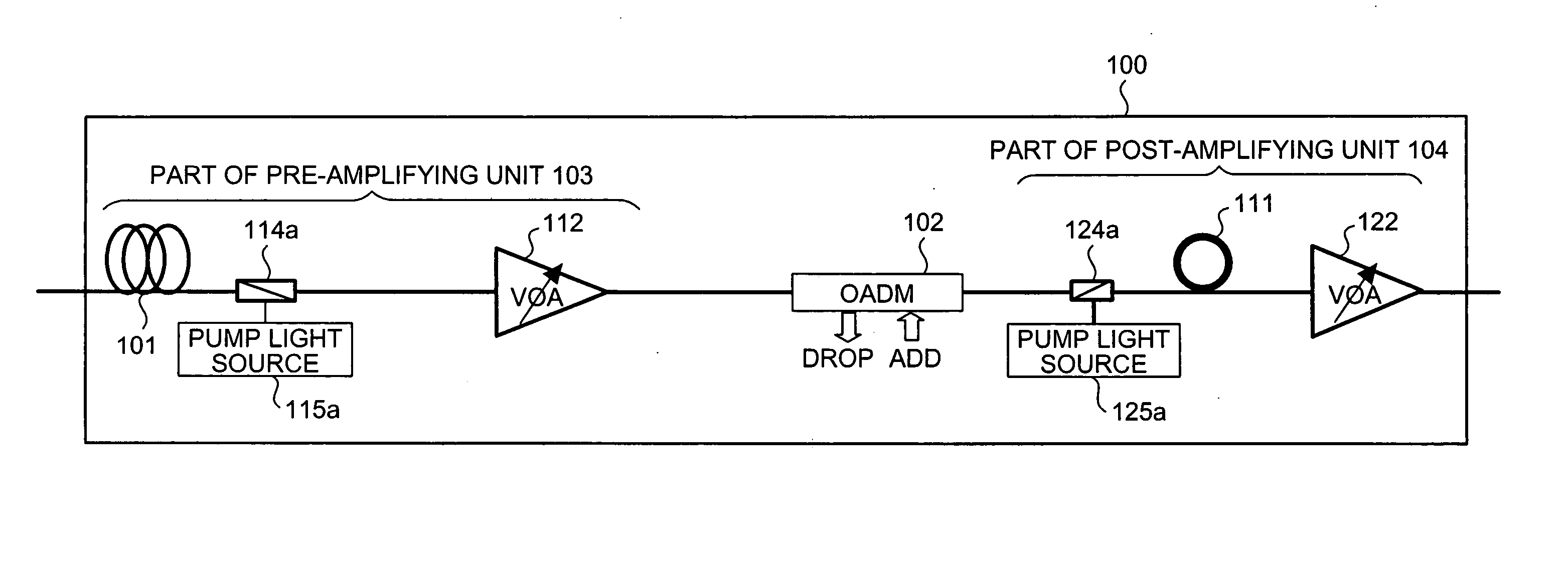
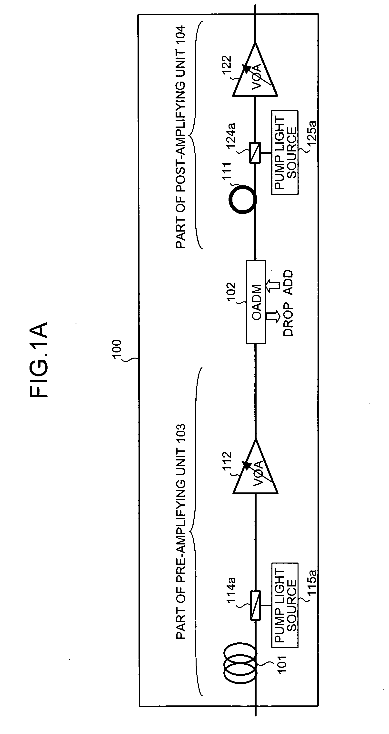
[0043]FIG. 1A is a configuration diagram of an optical transmission apparatus when a pump light source is disposed at a post-stage of a dispersion compensation fiber according to the present invention. FIG. 1A depicts the configuration of one node n (any one of the nodes n1 to nm) in the OADM system shown in FIG. 10. A transmission path 101, a pre-amplifying unit 103, an OADM 102, and a post-amplifying unit 104 are disposed in this order from the upstream (left side) in a node 100.

[0044] The OADM 102 optionally drops a wavelength-multiplexed optical signal from the transmission path 101, or adds a wavelength-multiplexed optical signal to the transmission path 101 to the OADM 102. While arrayed waveguide gratings (AWGs) are conventionally used, a wavelength selective switch (WSS) is used recently. When this WSS is used, the insertion loss in the OADM 102 can be decreased substantially as described in detail later.

[0045] The pre-amplifying unit 103 includes a pump light multiplexer 1...

second embodiment

[0077] In the second embodiment, at the upgrading time, the expansion part 301 is additionally provided in the pre-amplifying unit 103, and the expansion part 302 is additionally provided in the post-amplifying unit 104, in a similar manner to that shown in FIG. 3. Further, at the upgrading time, the optical amplifier in the pre-amplifying unit 103 has two stages. An optical amplifier 701 is additionally provided at the pre-stage of the optical amplifier 112 disposed at the initial introduction time, and a variable dispersion compensator (VDC) 702 is disposed between the pair of optical amplifiers 701 and 112.

[0078] The VDC 702 is effective to decrease the menu of the dispersion compensation fiber 111. However, the VDC 702 as a single unit has a limit to dispersion that can be compensated for. When the transmission path 101 has a long distance, the VDC 702 as a single unit cannot achieve a required level of dispersion compensation. Therefore, the dispersion compensation fiber 111 th...

third embodiment

[0088] As explained above, the power of the optical signal input to the pre-amplifying unit 103 in the node n (n2) at the downstream of the transmission path 101 is monitored using the up and down OSC links, thereby controlling the optical amplifier 122 in the post-amplifying unit 104 in the node n (n1) at the upstream of the transmission path 101 to automatically adjust the output of the post-amplifying unit 104.

[0089]FIG. 9 is a configuration diagram of an optical transmission apparatus according to a fourth embodiment of the present invention. In the fourth embodiment, another application example of the VDC 702 explained in the second embodiment (see FIG. 7) is explained.

[0090] In FIG. 9, a VDC 900 includes an optical circulator 901 and a variable dispersion compensating unit 902 disposed at the input side of the optical signal, as a general configuration. The variable dispersion compensating unit 902 includes an output end (ferule) 912 of the transmission path 101, a collimati...


PUM


Abstract

An optical transmission apparatus includes an optical add drop multiplexer (OADM) that adds / drops an optical signal to / from a transmission path. The optical transmission apparatus further includes a pump light multiplexer and a dispersion compensation fiber that are located downstream of the OADM on the transmission path. The optical transmission apparatus is configured to house a pump light source connectable to the pump light multiplexer to Raman amplify an optical signal in the dispersion compensation fiber.

Description

CROSS-REFERENCE TO RELATED APPLICATIONS [0001] This application is based upon and claims the benefit of priority from the prior Japanese Patent Application No. 2005-096531, filed on Mar. 29, 2005, the entire contents of which are incorporated herein by reference. BACKGROUND OF THE INVENTION [0002] 1. Field of the Invention [0003] The present invention relates to an optical transmission apparatus for a large-capacity and long-distance optical transmission system. [0004] 2. Description of the Related Art [0005] Along the development of a multimedia network, demand for communication traffic is increasing dramatically, and a transmission system that carries out multiple relay and amplification of an optical signal using an optical amplifier plays an important role of economizing a communication system in a multimedia society. [0006] Recently, a wavelength division multiplexing (WDM) system is actively introduced in a metro core network in which cost and size are important factors. A syn...

Claims


Application Information

Patent Timeline
Patent Type & Authority Applications(United States)
IPC IPC(8): H04J14/02H04B10/00H04B10/077H04B10/079H04B10/2507H04B10/2525H04B10/2537H04B10/2543H04B10/27H04B10/29H04B10/296H04B10/297H04J14/00
CPCH04B10/296H04B2210/003H04J14/0221H04J14/0201H04J14/0212H04B2210/256
Inventor ONAKA, MIKISUGAYA, YASUSHIOOI, HIROKI
Owner FUJITSU LTD
Why Eureka
Try Eureka