Performance prediction method for hydrocarbon recovery processes

a hydrocarbon recovery and performance prediction technology, applied in the direction of instruments, computation using denominational number representation, borehole/well accessories, etc., can solve the problems of complex operation of such a patterned flood, difficult computation, and difficult allocation of expensive miscible solvent among injectors

Active Publication Date: 2006-10-05
EXXONMOBIL UPSTREAM RES CO
View PDF9 Cites 114 Cited by
  • Summary
  • Abstract
  • Description
  • Claims
  • Application Information

AI Technical Summary

Benefits of technology

[0022] The first embodiment of the invention includes a method for predicting performance of a patterned flooding process in a subterranean hydrocarbon-bearing formation, the formation being penetrated by a plurality of injector wells and producer wells, comprising the steps of: determining flow-based pairs of injector to producer wells (first well pairs) using a geological model; developing a connective pore volume distribution curve for each first well pair; selecting at least two first well pairs (selected well pairs) that reflect narrow and wide connective pore volume distributions that correspond to high and lower oil recovery levels; developing a 3-D simulation model for each selected well pair; performing a reservoir simulation for each selected well pair for the corresponding flooding process; and generating prototype performance curves for each selected well pair.
[0023] A second embodiment of the invention includes a method for predicting performance of a patterned flooding process in a subterranean hydrocarbon-bearing formation, said formation being penetrated by a plurality of injector wells and producer wells, comprising the steps of: generating type-curve correlation equations for two or more well types; providing a single-phase, 2-D model of at least a portion of the subterranean formation; initializing said single-phase, 2-D model for initial pressure and initial oil saturation at the start of the patterned flooding process; determining flow-based pairs of injector to producer wells (second well pairs) using said single-phase, 2-D model of at least a portion of the hydrocarbon-bearing formation; determining for each second well pair a second processing rate and second pore volume; assigning to each second well pair one set of said type-curve correlation equations; calculating second cumulative injection for each second well pair using said second well pair's second processing rate and second pore volume; calculating second cumulative fluid production for each said second well pair from said second well pair's assigned type-curve correlation equations; estimating a second oil saturation in the single phase, 2-D model grid cells based on a tracer simulation representative of the formation before a modification; modifying injection well location, production well location, a process parameter, or a well processing rate; re-determining flow-based pairs of injector to producer wells (third well pairs) using said single phase, 2-D model of at least a portion of the hydrocarbon-bearing formation and re-calculating for each third well pair a third processing rate and third pore volume; calculating a new starting point on the type-curve correlation equations using the initial oil saturation and the second oil saturation; and using said third processing rate, said third pore volume, and said type-curve correlation equations to predict fluid production for each said third well pair for predetermined time intervals.

Problems solved by technology

The operation of such a patterned flood can be complex, because fluid flows from injectors to producers in the reservoir are complex and interacting.
In addition, for EOR processes such as miscible gasfloods the allocation of expensive miscible solvent among injectors is not straightforward.
The computation is especially complicated for EOR processes such as miscible gas flooding that requires multiple components to characterize the oil and gas phases.
Due to its lengthy computation, it is often not used for making operating decisions in day-to-day management of large pattern floods, especially for EOR processes.
The slower computation limits the application of compositional streamline simulation for managing large-scale pattern miscible gasfloods.
However, it is oversimplified due to the use of geometric injector-producer polygons and geometric fluid allocations.
Consequently, its predictive capability is highly limited.
While this method is more accurate than those based strictly on geometric fluid allocation, it cannot respond to dynamic changes of well locations and rates.
The conventional production type-curve scale-up methods of the prior art provide less than desirable results for two reasons.
First, the use of geometric polygons results in erroneous fluid allocations and poor predictive capabilities.
Second, the use of fixed geometric polygons do not handle dynamic changes to well rates and locations.
However, it cannot handle changes to well rates, locations, and key process parameters such as solvent bank size.
However, the expression of prototype production through the tracer adsorption and desorption formulation limits the flexibility of handling key process parameters, such as WAG, VGR and well flow rates.

Method used


Image

  • Performance prediction method for hydrocarbon recovery processes
  • Performance prediction method for hydrocarbon recovery processes
  • Performance prediction method for hydrocarbon recovery processes

Examples


Embodiment Construction

[0039] The following description and claims make use of mathematical symbols, many of which are defined as they occur in this description. Additionally, for purposes of completeness, a table containing definitions of symbols used herein is presented following the detailed descriptions. Before proceeding, definitions of principal terms used in the description and claims are provided to aid the reader in understanding the invention.

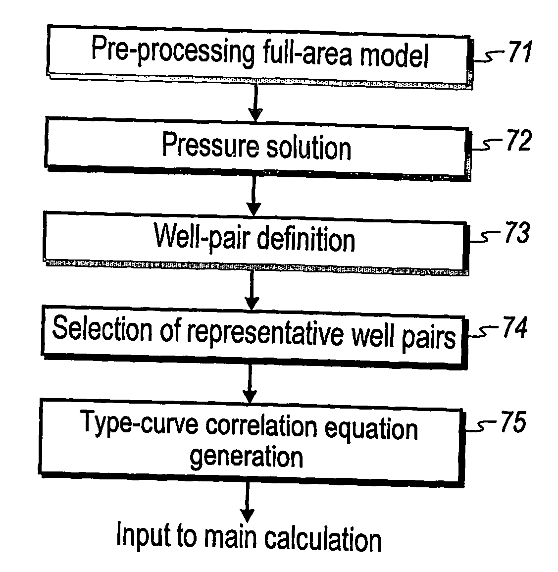
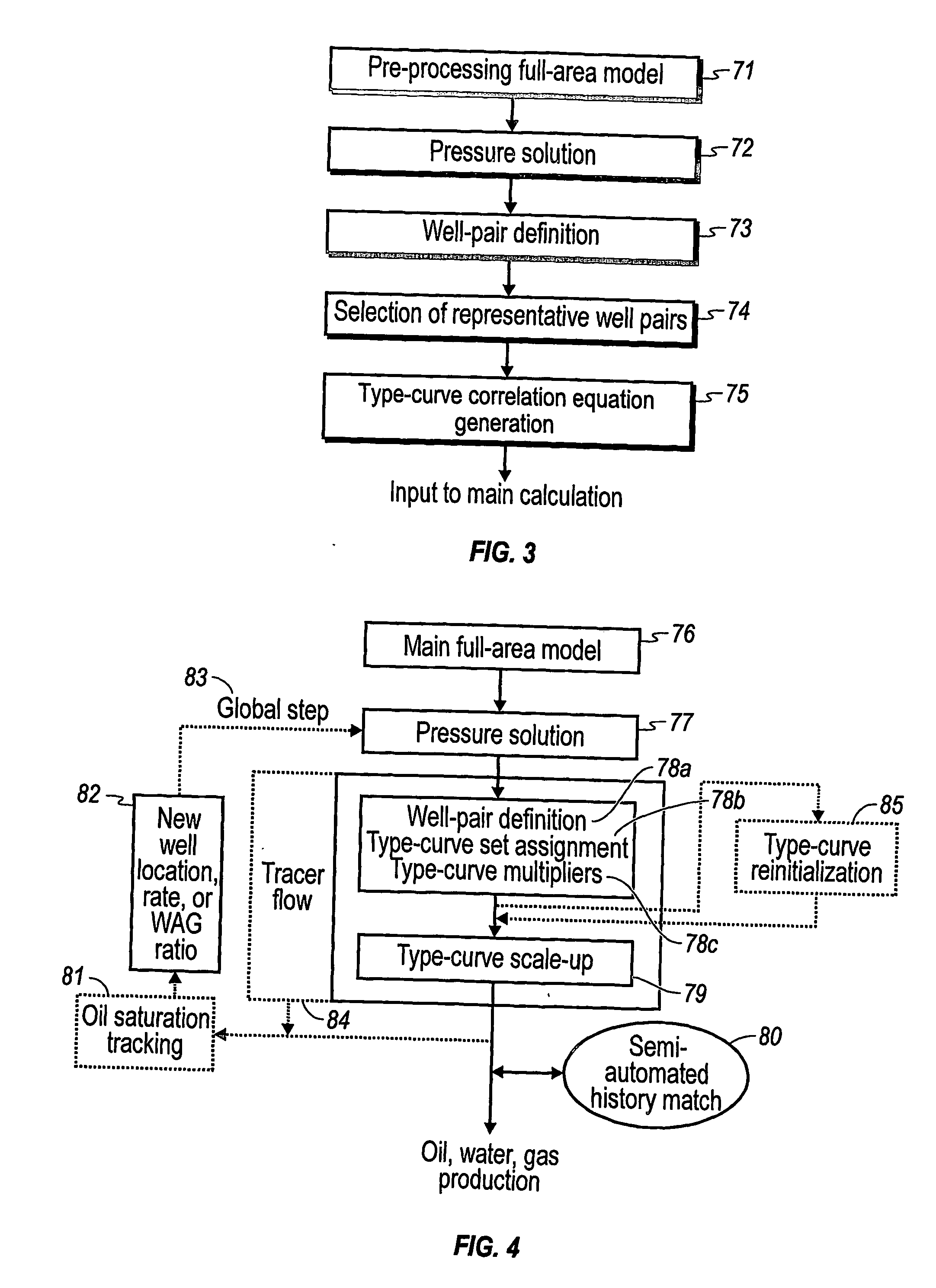
[0040] CPVD is an acronym for connected pore volume distribution that is further detailed in the section on selection of representative well pairs.

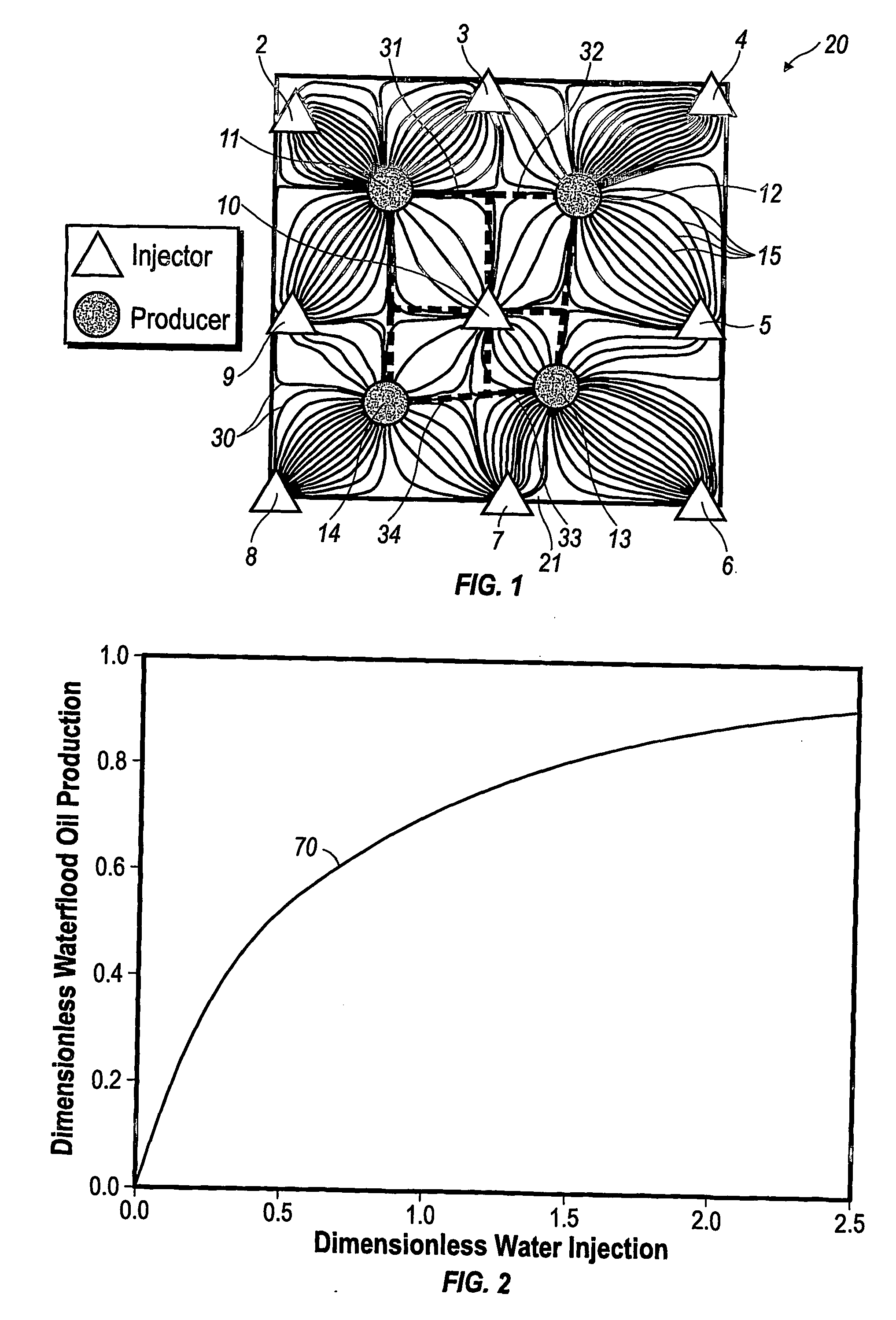
[0041] Element model means a small flow model that represents a fraction of a flood pattern and contains at least one injector-producer pair.

[0042] Flow-based injector-producer pair is defined as an injector and producer well pair connected by flow streamlines. For example, FIG. 1 illustrates an example of 16 injector-producer pairs. In FIG. 1 fluid allocations from the center injector to the four surrounding ...


PUM


Abstract

The invention relates to a method for predicting the performance of large-scale hydrocarbon-bearing reservoir floods. One embodiment of the invention includes a method for predicting performance of a patterned flooding process in a subterranean hydrocarbon-bearing formation, said formation being penetrated by a plurality of injector wells and producer wells, comprising the steps of: determining flow-based pairs of injector to producer wells [FIG. 4, item 78a] (first well pairs) using a geological model [item 76]; developing a connective pore volume distribution curve for each first well pair item [78b]; selecting at least two first well pairs (selected well pairs) that reflect narrow and wide connective pore volume distributions that correspond to high and lower oil recovery levels; developing a 3-D simulation model for each selected well pair, performing a reservoir simulation for each selected well pair for the corresponding flooding process; and generating prototype performance curves for each selected well pair. An alternate embodiment of the invention includes a method for predicting the performance of large-scale hydrocarbon-bearing reservoir floods where injection well location, production well location, a process parameter, or a well processing rate is modified.

Description

CROSS REFERENCE TO RELATED APPLICATIONS [0001] This application claims the benefit of U.S. Provisional Application 60 / 457,718, filed Mar. 26, 2003.FIELD OF THE INVENTION [0002] The invention relates generally to a method for predicting the performance of large-scale hydrocarbon-bearing reservoir floods. BACKGROUND [0003] Performance prediction plays an important role in the management of large-scale waterfloods and miscible gasfloods. Computer simulation methods / tools are used to predict the ultimate recovery of hydrocarbons in the design of a flooding process and optimization of flooding operations. Typically, a large number of injectors and producers are aligned in patterns in a patterned flood. The operation of such a patterned flood can be complex, because fluid flows from injectors to producers in the reservoir are complex and interacting. Displacement performance within a given pattern is often influenced by the injection activities and production activities of surrounding flo...

Claims


Application Information

Patent Timeline
Patent Type & Authority Applications(United States)
IPC IPC(8): G06G7/48G01V11/00G06F7/48G06F17/10
CPCE21B43/16G01V11/00E21B47/1015E21B43/20E21B47/11Y02A10/40
Inventor YANG, SHANHMIERTSCHIN, JOHN W.KUDVA, RYAN A.ARBABI, SEPEHR
Owner EXXONMOBIL UPSTREAM RES CO
Why Eureka
Try Eureka