
Method, system, and apparatus for handling, labeling, filling and capping syringes

a technology for filling and capping syringes, applied in the field of handling syringes, can solve problems such as difficulty in keeping pressure sensitive labels in place, and achieve the effect of improving the filling and capping approach and facilitating the maintenance of sterility

Inactive Publication Date: 2006-10-12
BAXTER ENGLEWOOD
View PDF83 Cites 6 Cited by
  • Summary
  • Abstract
  • Description
  • Claims
  • Application Information

AI Technical Summary

Benefits of technology

[0009] In view of the foregoing, a broad objective of the present invention is to provide a method, system and apparatus for enhanced syringe handling. A closely related objective is to facilitate automated syringe handling for various operations, such as syringe filling, labeling and capping.
[0010] Another objective of the present invention is to provide a syringe handling approach that facilitates the maintenance of sterility.

Problems solved by technology

Some medications provided by pharmaceutical manufacturers are prepared, stored, and shipped as powders, crystals, or some other solid form due to the lack of stability in solution.
However, larger health care institutions often administer medications in syringes to hundreds of patients per day, thus requiring the rather large chore of filling hundreds of syringes with medications and labeling each filled syringe to show the contents, strength, and fill dates, usually under the direction of a qualified pharmacist.
Often, this migration causes difficulties in getting pressure sensitive labels to stay in place.
Efforts to automate hospital or clinic-based syringe preparation have been made, but most systems have automated only portions of the process and still require human intervention during critical stages of the process.

Method used


Image

  • Method, system, and apparatus for handling, labeling, filling and capping syringes
  • Method, system, and apparatus for handling, labeling, filling and capping syringes
  • Method, system, and apparatus for handling, labeling, filling and capping syringes

Examples


Embodiment Construction

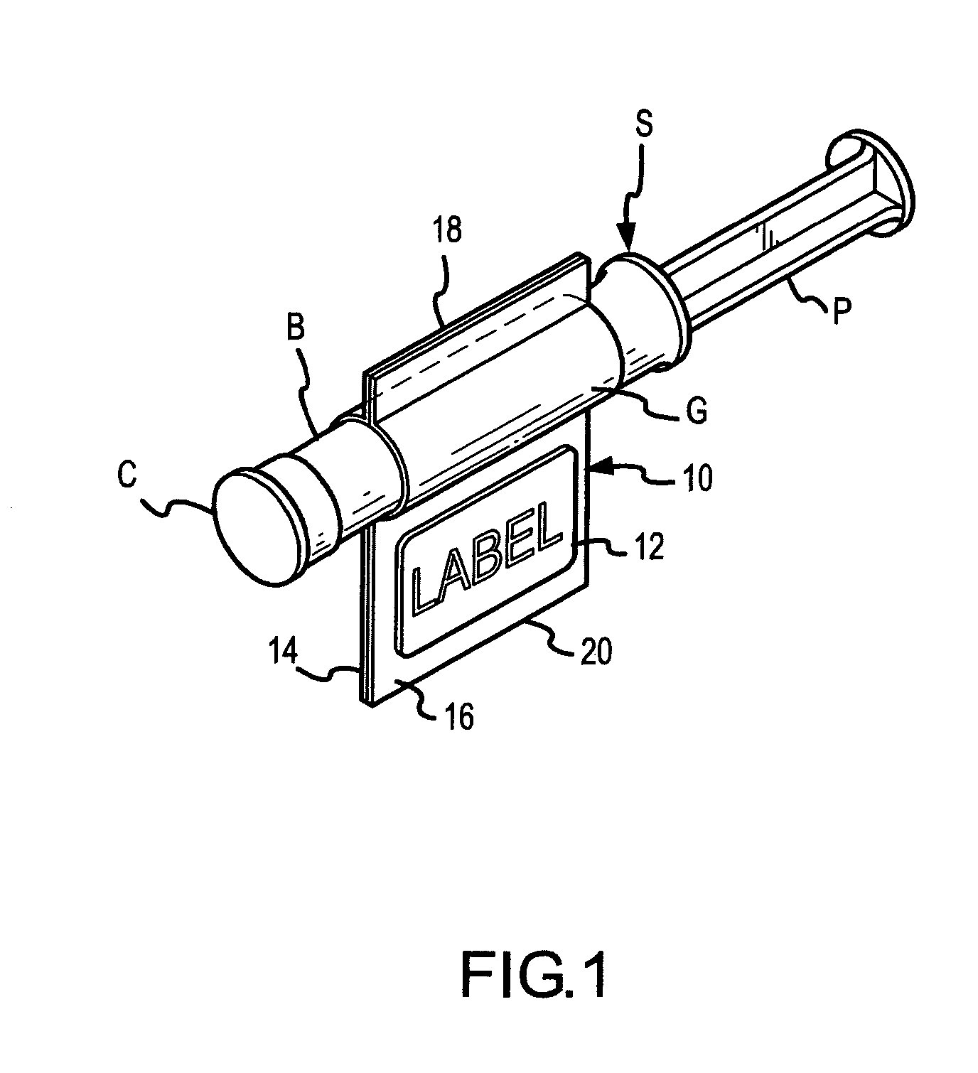
[0066] A capped syringe S that has been labeled and filled according to one embodiment of this invention is shown in FIG. 1. A cap C covers and protects the sterility of the dispensing luer tip (concealed from view in FIG. 1 by the cap C). Since the barrel B of the syringe S is full in FIG. 1, the plunger P is extended longitudinally. A flap or substrate 10 for a label 12 is provided by two strips of adhesive tape 14, 16, both of which are wrapped around and adhered to respectively opposite sides of the barrel B and adhered to each other in face-to-face relation in extensions 18, 20 of the adhesive tape 14, 16 that extend in diametrically opposite directions from the barrel B. It is preferred, but not necessary, that at least one of the adhesive tapes 14, 16 be transparent so that the graduation marks G that are on most conventional syringes as well as the plunger piston (not shown) in FIG. 1) can be seen through the adhesive tape.

[0067] In the embodiment shown in FIG. 1, the label...


PUM

PropertyMeasurementUnit
flexibleaaaaaaaaaa
volumeaaaaaaaaaa
distanceaaaaaaaaaa

Abstract

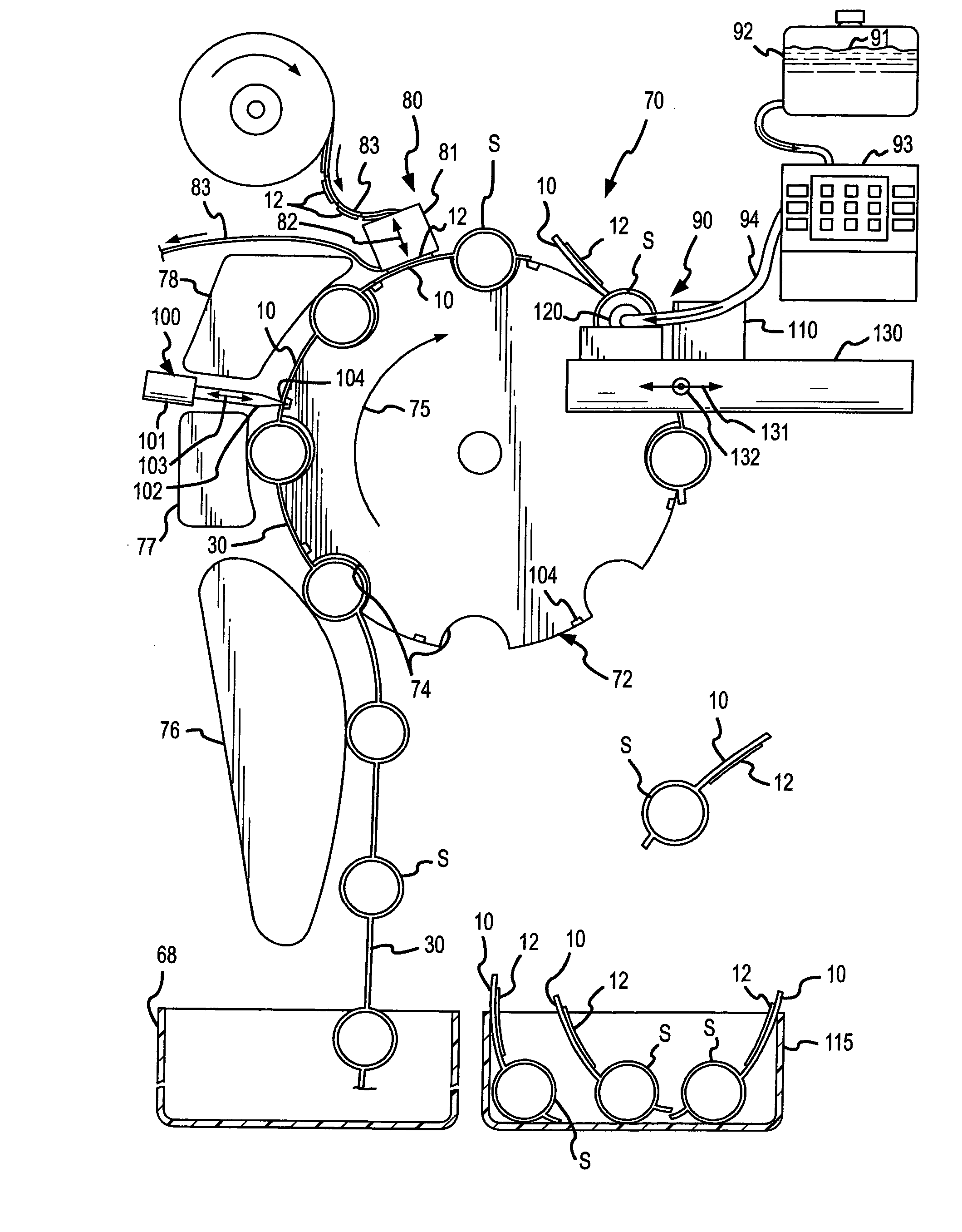
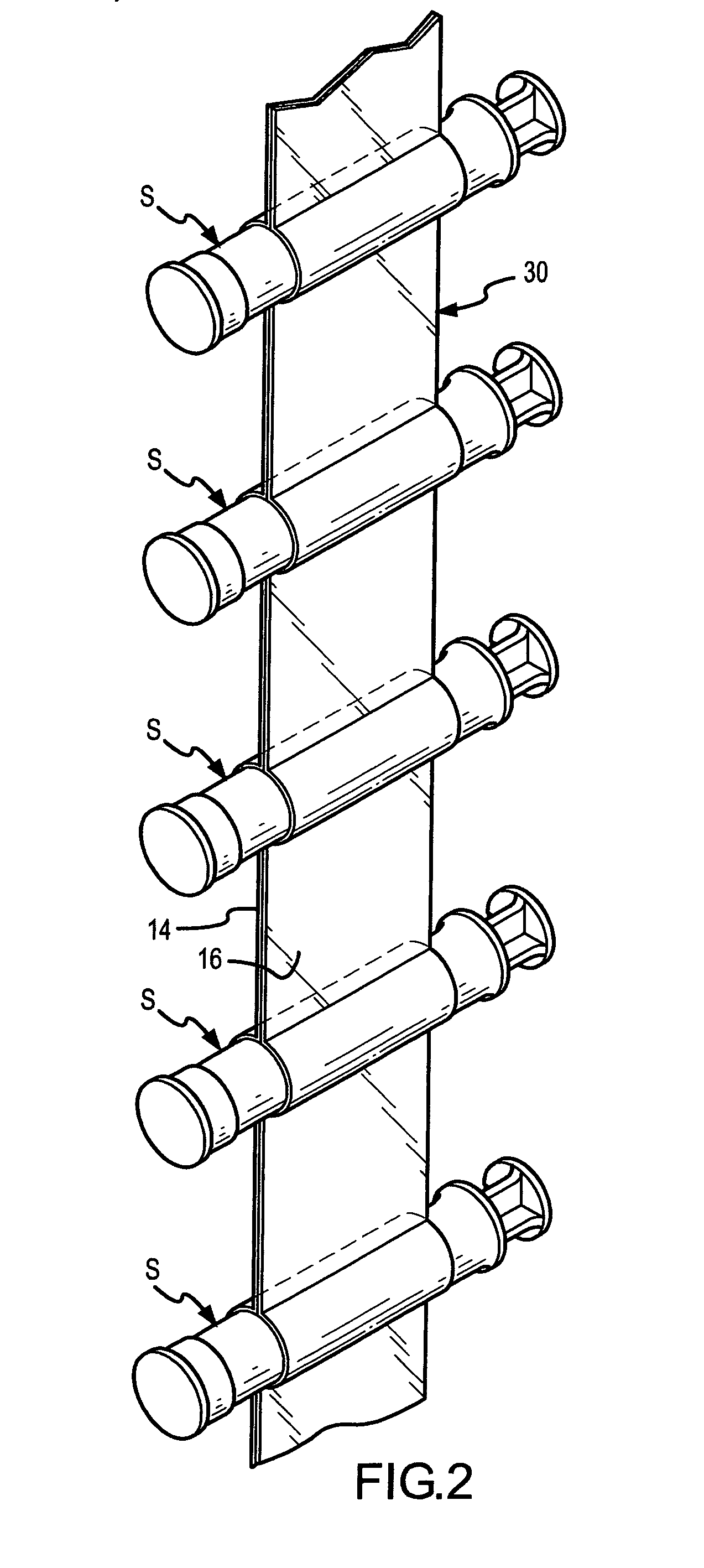
An inventive method, system and apparatus are provided for syringe handling, and more particularly, for syringe labeling, filling and capping operations. To facilitate syringe handling, an inventive apparatus includes a plurality of syringe bodies interconnected in a predetermined orientation by a belt. Such belt may be of pliable construction and may define a predetermined spacing in between adjacent ones of the syringe bodies, such predetermined spacing corresponding with a distance between holders provided in a handling apparatus. The syringe handling apparatus may provide for the placement of contents-related information on belt segments between adjacent syringe bodies and for separating the belt segments, wherein a flap is left interconnected to each syringe body. The syringe handling apparatus may alternatively or also provide for automated filling of the syringe bodies wherein cap removal, filling and cap replacement operations are completed free from manual handling.

Description

RELATED APPLICATIONS [0001] This application is a divisional application of U.S. patent application Ser. No. 10 / 864,610 filed Jun. 9, 2004, which is a continuation of U.S. patent application Ser. No. 09 / 928,007 filed Aug. 10, 2001, now U.S. Pat. No. 6,813,868, which claims priority under 35 U.S.C. § 119 to U.S. Provisional Patent Application Ser. No. 60 / 224,136, filed Aug. 10, 2000. Each of the above-identified patent applications is hereby incorporated by reference in its entirety.FIELD OF THE INVENTION [0002] The present invention generally relates to the handling of syringes, and is particularly apt for use in automated syringe handling operations, such as syringe filling, labeling and capping operations. BACKGROUND OF THE INVENTION [0003] Each year countless syringes are used throughout the world by the healthcare industry for the administration of liquid medications to humans and animals with hypodermic needles or infusion catheters, as well as for delivery of oral and topical ...

Claims


Application Information

Patent Timeline
Patent Type & Authority Applications(United States)
IPC IPC(8): B65B61/02B65B3/00B65B9/02B65C3/06G09F3/02
CPCA61M5/28A61M2005/3104A61M2205/6072A61M2207/00B65B3/003B65B3/006A61J2205/30B65B9/02B65B55/04B65C3/06G09F3/02A61J2205/10B65B5/04
Inventor BALDWIN, BRIAN EUGENE
Owner BAXTER ENGLEWOOD
Learn More