Supercharge Your Innovation With Domain-Expert AI Agents!

Cam mechanism for low vibration air-driven screwdriver

a screwdriver and cam mechanism technology, applied in screwdrivers, wrenches, manufacturing tools, etc., can solve the problems of high vibration, high production cost, and high cost of special bearings, and achieve the effects of less vibration, long ser4vice life, and low production cos

Inactive Publication Date: 2006-10-12
MIJY LAND IND
View PDF4 Cites 0 Cited by
  • Summary
  • Abstract
  • Description
  • Claims
  • Application Information

AI Technical Summary

Benefits of technology

The invention provides an improved cam mechanism for low vibration air-driven screwdrivers that can be used in both rotation directions or single rotation direction with low production cost, less vibration, and longer service life. The cam body's orbital surface is designed with three segments, each containing a stroke from the top dead point to the bottom dead point, and each stroke provides curved recess for the catch ball to move along. These new designs reduce vibration to the minimum and increase friction area between the cam body and the catch ball to elongate the service life span.

Problems solved by technology

The merit of this design is low production cost and the demerit is high vibration.
The major merits are low vibration and easy operation, but the demerit is that the special bearing is expensive to make.
Regardless which cam mechanism is employed, the design of the orbital surface and the stroke between the top dead point and the bottom dead point is not immaculate, when in bolt tightening operation, it as usual generate a relative counter moment which would finally injure the arm of the operator after long time operation.

Method used


Image

  • Cam mechanism for low vibration air-driven screwdriver
  • Cam mechanism for low vibration air-driven screwdriver
  • Cam mechanism for low vibration air-driven screwdriver

Examples


Embodiment Construction

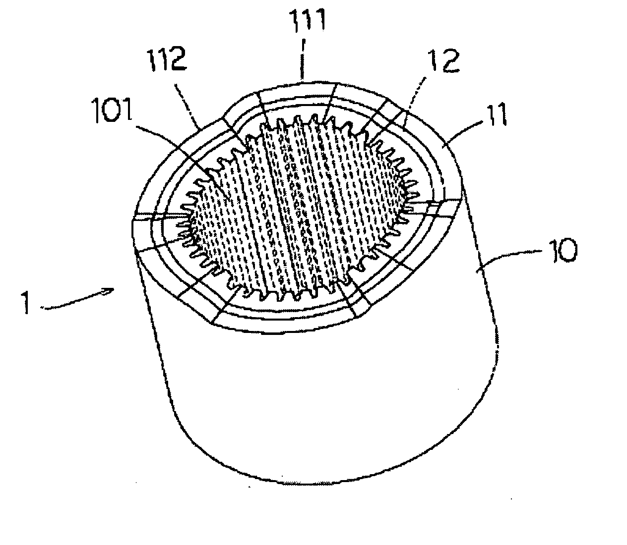
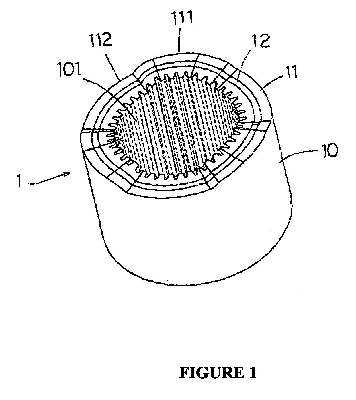
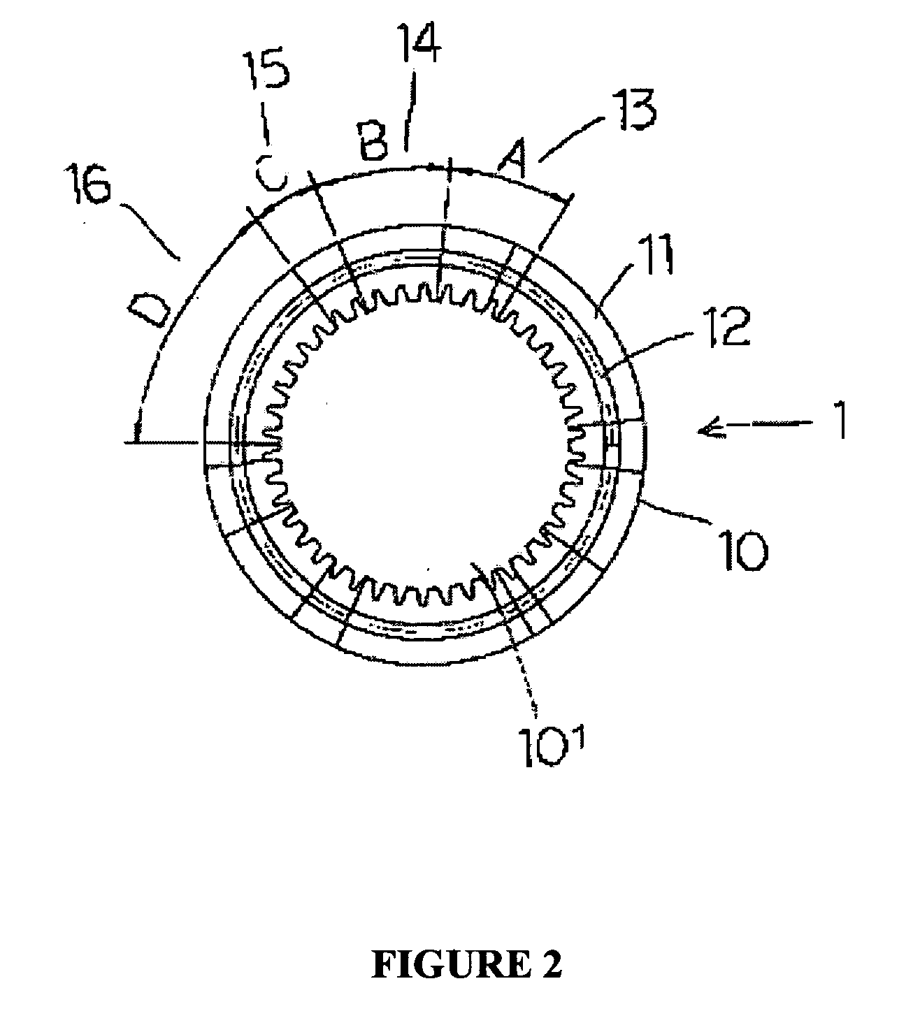
[0014] The improved cam mechanism as provided in this invention is both suitable for the electric and pneumatic screwdriver. As shown in FIG. 1, the cam mechanism (1) contains the body (10) and the shaft groove (101). The orbital surface (11) of the body (10) is divided into three segments, each segment contains a cyclic stroke from the top dead point (111) to the bottom dead point (112) and each stroke comprises four phases as shown in the FIG. 2.

[0015] Phase A (13) is employed to control the torque required for the electric or the pneumatic screwdriver. The stroke is designed with an outer R angle, differing from the general slant angle, so the axial reaction generated differs from that of the slant angle. In the slant angle design, the axial moment and the radical moment are 50% to 50%, that is to say 50% vibration generated in the start must be absorbed by the arm of the operator. In the outer R angle design, the axial moment amounts 25& and the radical moment, 75% which is abs...


PUM


Abstract

This invention related to an improved cam mechanism of low vibration air driven screwdriver, in particular, applicable to the clutch for the electric or pneumatic screwdriver in an effort to reduce the vibration to the minimum. The orbital surface of the cam body provides three segments of cyclic stroke, each stroke comprises the top dead point and the bottom dead point and each segment further contains four phases stroke, namely phase stroke A, phase stroke B, phase stroke C and phase stroke D. Each stroke of the orbital surface forms a recess for the catch ball to move. These two new designs are intended to reduce the vibration to the minimum and to cut the production cost in one way and to increase the friction area between the cam body and the ball so as to elongate the service life span in other way.

Description

BACKGROUND OF THE INVENTION [0001] 1. Field of the Invention [0002] This invention concerns a novel design of the cam mechanism, best applicable to the electric or pneumatic screwdriver in an attempt to reduce the vibration to the minimum, to cut down the production and to elongate the service life span. [0003] 2. Description of the Prior Art [0004] The cam mechanism of the clutch is commonly used in the electric or pneumatic screwdriver. The operational theory is that the catch ball in the lower clutch will rise from the bottom dead point to the top dead point along the orbital surface so as to activate the electrical or mechanism switch and to stop the power or air supply in an effort to control the torque of the screwdriver. When the torque is obtained, the torque spring will exert the pressure on the catch ball, the lower clutch and punch, the cam will fall from the top dead point to the bottom dead point, forming an 180° cycle. While the motor is running, the cam is forced to m...

Claims


Application Information

Patent Timeline
Patent Type & Authority Applications(United States)
IPC IPC(8): F16H53/00
CPCB25B23/14Y10T74/2101B25B23/141
Inventor LEE, TSUH CHANG
Owner MIJY LAND IND
Features
  • R&D
  • Intellectual Property
  • Life Sciences
  • Materials
  • Tech Scout
  • Unparalleled Data Quality
  • Higher Quality Content
  • 60% Fewer Hallucinations
Learn More