Suspension system for electric vehicle

Inactive Publication Date: 2006-10-12
TOYOTA JIDOSHA KK
View PDF5 Cites 21 Cited by
  • Summary
  • Abstract
  • Description
  • Claims
  • Application Information

AI Technical Summary

Benefits of technology

[0004] Therefore, it is an object of the present invention to improve rid

Problems solved by technology

In this conventional suspension system, since the motor is directly connected to the wheel, an unsprung mass increases by the amount

Method used


Image

  • Suspension system for electric vehicle
  • Suspension system for electric vehicle
  • Suspension system for electric vehicle

Examples


first embodiment

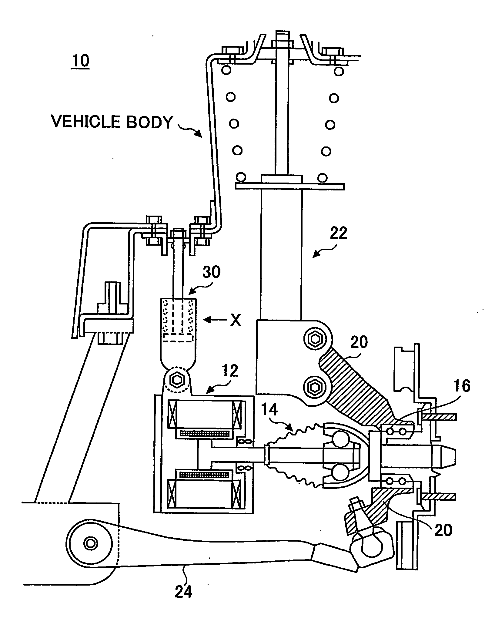
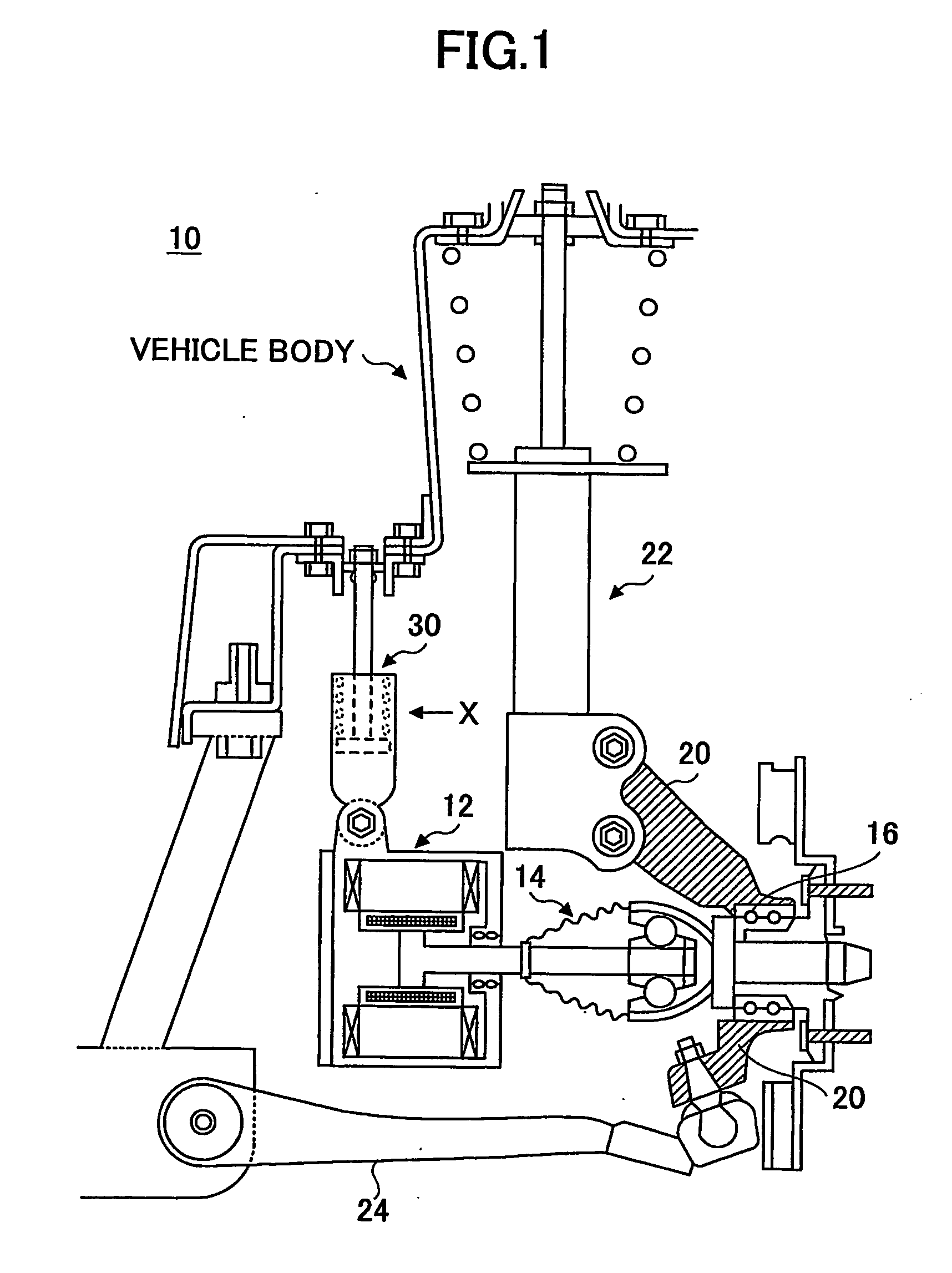
[0030]FIG. 1 is a schematic front view of a suspension system according to the present invention. The suspension system 10 according to this embodiment has a motor 12 for driving a wheel. Every driven wheel is provided with one of the motors 12 and a braking system (e.g., a caliper and a disk rotor) shown in part. A steering system (e.g., a tie rod) is provided for steering the wheel. Explanation is made below for only one driven wheel, since there is substantially no difference in arrangement between the wheels. However, it is noted that the arrangement according to this embodiment may be applied to only front wheels or only rear wheels.

[0031] A rotating shaft of the motor 12 is connected to the driven wheel via a drive shaft (including a constant velocity joint) 14 that passes through a knuckle (steering knuckle) 20. The drive shaft 14 is rotatably supported inside the knuckle 20 by way of a bearing 16. To the knuckle 20 is coupled a lower end of a suspension 22 which mainly inclu...

fourth embodiment

[0046] Next, a suspension system 10 according to the present invention is described with reference to FIGS. 7 and 8.

[0047]FIG. 7 is a schematic perspective view of the suspension system 10 according to this embodiment. The suspension system 10 according to this embodiment has a motor 12 for driving a wheel. Every driven wheel is provided with the motor 12 and a braking system (e.g., a brake shoe 50, etc.) shown in part. A steering system (e.g., a tie rod 54) is provided for steering the wheel. Explanation is made below for only one wheel, since there is substantially no difference in arrangement between the wheels. However, it is noted that the arrangement according to this embodiment may be applied to only front wheels or only rear wheels.

[0048] The motor 12 according to this embodiment is supported by the vehicle body via a suspension 30, which includes a shock absorber and a coil spring, such that the motor 12 can move in up-and-down directions with respect to the vehicle body, ...


PUM


Abstract

A suspension system (10) for a vehicle for suspending a wheel (1) is disclosed. The suspension system (10) includes a motor (12) for driving the wheel of the vehicle; a first suspension (22) for supporting the wheel (1) of the vehicle with respect to the vehicle body; a second suspension (30) for elastically supporting the motor (12) with respect to the vehicle body; and a power transferring mechanism (14) for transferring power from the motor (12) to the wheel (1) while permitting relative movement of the motor (12) with respect to the wheel (1).

Description

TECHNICAL FIELD [0001] The present invention relates to a suspension system for a vehicle that utilizes the power of motors for driving wheels. BACKGROUND ART [0002] JP2000-16040 A discloses a suspension system for use in a vehicle, wherein a motor for driving the wheel is provided inside the wheel. With this arrangement, thanks to arranging the motor within the wheel, it is possible to make advantageous use of space within the wheel as well as to reduce the weight of a mechanism for transferring the driving power generated from the motor to the wheel. [0003] In this conventional suspension system, since the motor is directly connected to the wheel, an unsprung mass increases by the amount of the motor and components associated therewith, resulting in a deterioration in a road holding characteristic and thus ride quality. DISCLOSURE OF INVENTION [0004] Therefore, it is an object of the present invention to improve ride quality of a vehicle that utilizes power of a motor for driving ...

Claims


Application Information

Patent Timeline
IPC IPC(8): B60K1/00B60K17/356B60K8/00B60K7/00
CPCB60G2200/142B60G2200/422B60G2202/24B60G2202/25B60G2202/42B60L2220/46B60G2300/50B60K7/0007B60K17/043B60K2007/0053B60K2007/0061B60G2204/182
Inventor KURATA, FUMITO
Owner TOYOTA JIDOSHA KK
Why Eureka
Try Eureka