
Laser welding method and laser welding robot

Inactive Publication Date: 2006-10-12
FANUC LTD
View PDF8 Cites 13 Cited by
  • Summary
  • Abstract
  • Description
  • Claims
  • Application Information

AI Technical Summary

Benefits of technology

[0010] The object of the present invention is to provide a laser welding method and a laser welding robot which can shorten the cycle time of the welding process and improve the work efficiency.

Problems solved by technology

For this reason, in the same way as resistance welding, the work becomes poor in work efficiency.

Method used


Image

  • Laser welding method and laser welding robot
  • Laser welding method and laser welding robot
  • Laser welding method and laser welding robot

Examples


first embodiment

[0027] Below, preferred embodiments of the present invention will be explained in detail with reference to the drawings. FIGS. 1-3 are views for explaining a laser welding method and laser welding robot according to the present invention.

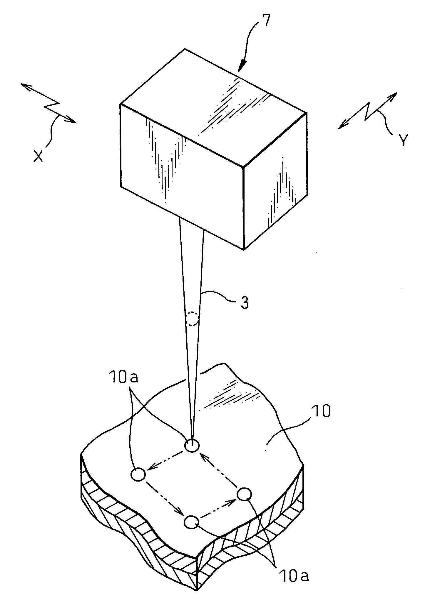
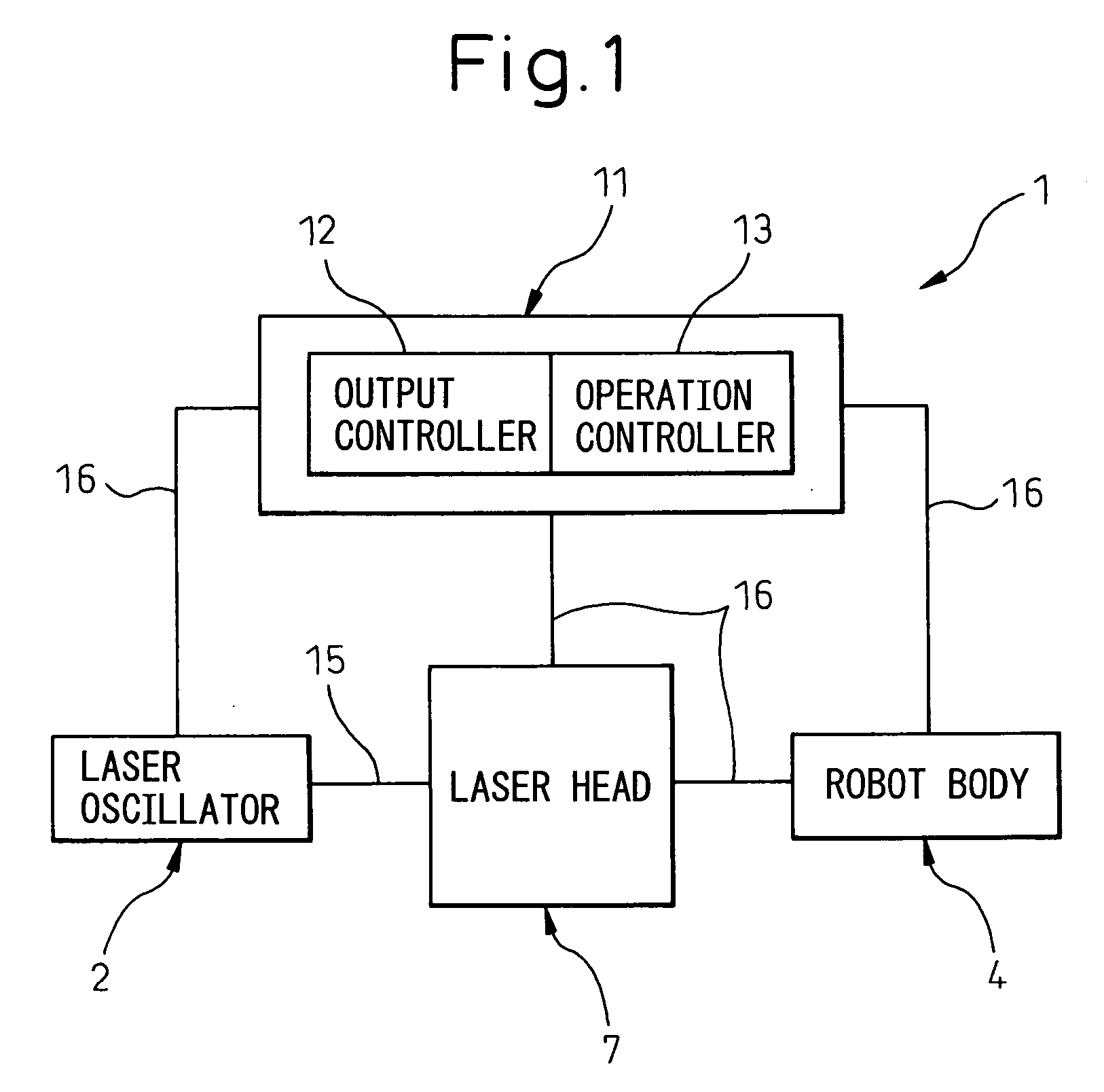
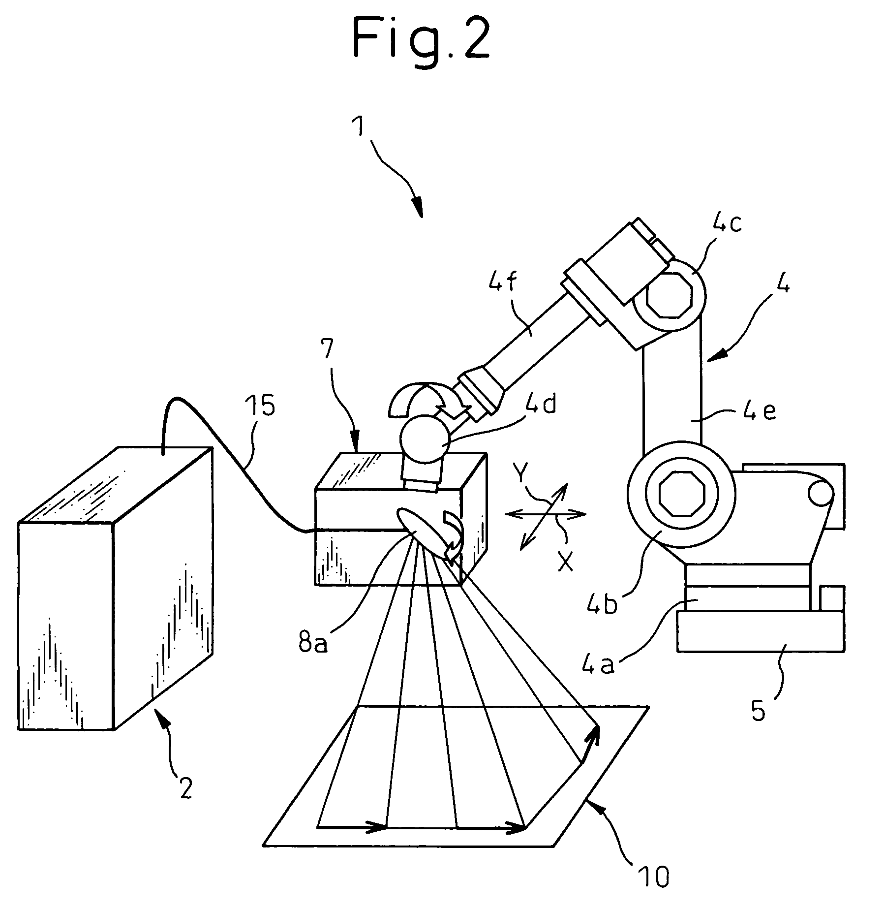
[0028] As shown in FIG. 1 and FIG. 2, a laser welding robot 1 of this embodiment is provided with a robot body 4 as a so-called multi-articulated manipulator having a plurality of controllable control axes, a laser oscillator 2 amplifying and discharging a laser beam 3 (see FIG. 3), a laser head 7 mounted at the front end of the robot body 4 and firing the laser beam 3 at the workpiece 10, and a control system 11 controlling the laser oscillator 2 etc. (not shown in FIG. 2).

[0029] The laser oscillator 2 is comprised of an excitation source (not shown) for supplying energy to the laser medium and a resonator (not shown) having laser medium and two mirrors of different light transmittances at the two sides of the laser medium. The laser oscillator 2 ...

second embodiment

[0048] As explained above, even if firing the laser beam 3 at the time of not welding, it is possible to defocus the laser beam 3 from the workpiece 10 so as to enlarge the diameter of the spot of the laser beam 3 and thereby reduce the energy density at the position where the laser beam 3 is fired and prevent surface degradation of the workpiece 10. Therefore, it is possible to shorten the work cycle time and improve the work efficiency without impairing the surface quality of the workpiece 10.

[0049] Note that the present invention is not limited to the above embodiments and can be modified in various ways within a scope not departing from the framework of the present invention. For example, the laser output control mechanism 12 is provided in the control system 11, but may also be provided in the laser oscillator 2.

[0050] Further, in the first embodiment, the laser beam 3 is moved at a fast speed by the movable mirror 8a of the laser head 7, but laser head 8 may also be moved by...


PUM

PropertyMeasurementUnit
Timeaaaaaaaaaa
Feed rateaaaaaaaaaa

Abstract

A laser welding method using a laser welding robot irradiating a workpiece with a laser beam, the laser welding method has firing the laser beam at a time of not welding, making the laser beam move to the next weld location at a feed rate faster than the feed rate at a time of welding and not leaving a heat affected layer at the workpiece in a state while firing the laser beam, and successively welding a plurality of weld locations of the workpiece. It is possible to make the laser beam move at the time of not welding while defocused. Also, a laser welding robot irradiating a workpiece with a laser beam, provided with a laser output controller controlling the robot to fire a laser beam both at a time of welding and at a time of not welding and fast feed mechanisms for making the laser beam move by a feed rate faster than the feed rate at the time of welding and not leaving a heat affected layer at the workpiece. It is possible to make the fast feed mechanism move simultaneously with movement of the robot body.

Description

BACKGROUND OF THE INVENTION [0001] 1. Field of the Invention [0002] The present invention relates to a laser welding method and laser welding robot to weld a plurality of locations of a workpiece while moving a laser beam. [0003] 2. Description of the Related Art [0004] The laser welding method using a welding robot to move a laser head to weld a plurality of locations of a workpiece is being used as technology taking the place of resistance welding in production lines of automobiles etc. Resistance welding is welding sandwiching overlaid metal members by the front ends of electrodes, running a current while applying a pressing force to the weld location, and thereby partially bonding them. In resistance welding, when the workpiece includes a plurality of weld locations, the welding work is performed intermittently. For this reason, with this type of work, the wider the scope of the work, the larger the ratio of the non-working time in the cycle time of one step of work. [0005] Even...

Claims


Application Information

Patent Timeline
IPC IPC(8): B23K26/22
CPCB23K26/0884
Inventor OTSUKA, KAZUHISAFURUYA, YOSHITAKE
Owner FANUC LTD
Features
  • Generate Ideas
  • Intellectual Property
  • Life Sciences
  • Materials
  • Tech Scout
  • Unparalleled Data Quality
  • Higher Quality Content
  • 60% Fewer Hallucinations
Learn More