Vane assembly with metal trailing edge segment

a technology of trailing edge segment and vane, which is applied in the direction of machines/engines, air-flow influencers, liquid fuel engines, etc., can solve the problem that no single material is ideal for every portion of the van

Inactive Publication Date: 2006-10-12
SIEMENS ENERGY INC
View PDF52 Cites 74 Cited by
  • Summary
  • Abstract
  • Description
  • Claims
  • Application Information

AI Technical Summary

Benefits of technology

[0010] In one embodiment, at least a portion of each of the interface surfaces can be substantially correspondingly tapered. Further, the forward airfoil segment can be radially biased such that the respective interface surface is urged toward the other interface surface, thereby holding the sealing device in compression. In one embodiment, the interface surfaces can be substantially matingly serpentine. Thus, the serpentine interface surfaces can create a tortuous gap between the forward and aft airfoil segments so as to impede flow through the gap.

Problems solved by technology

However, at least from a thermal design standpoint, experience has demonstrated that no single material is ideal for every portion of the vane.

Method used


Image

  • Vane assembly with metal trailing edge segment
  • Vane assembly with metal trailing edge segment
  • Vane assembly with metal trailing edge segment

Examples


Embodiment Construction

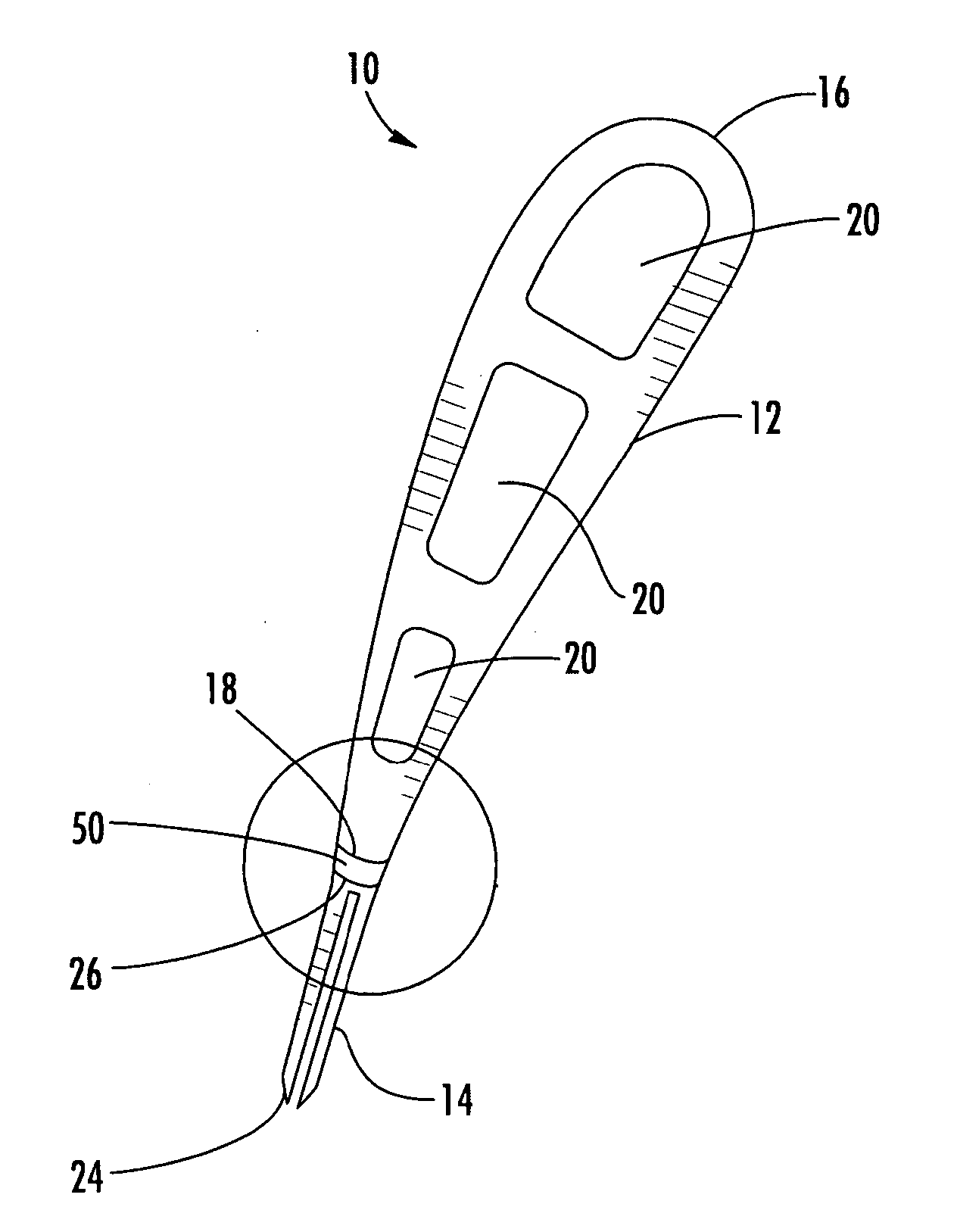
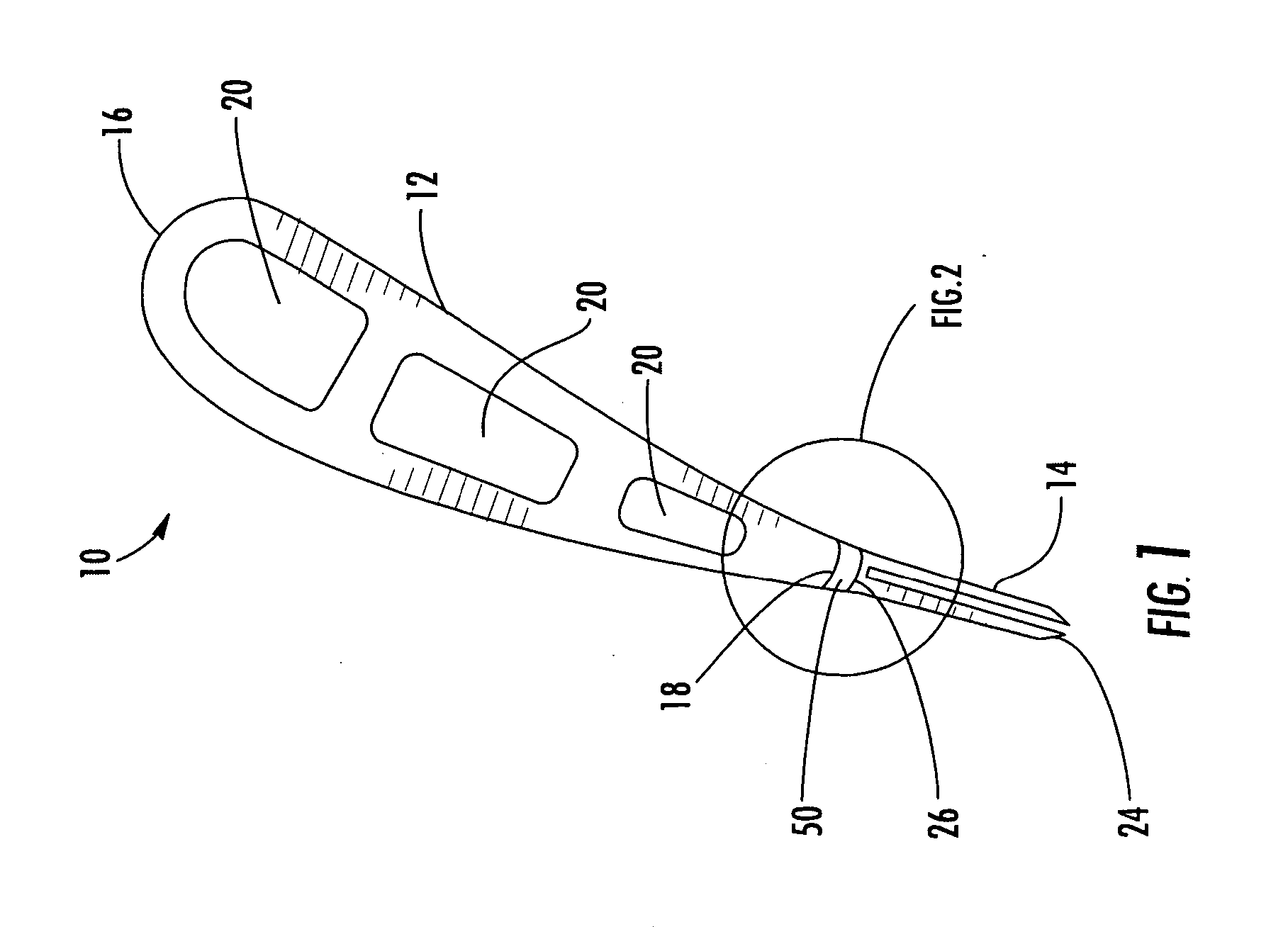
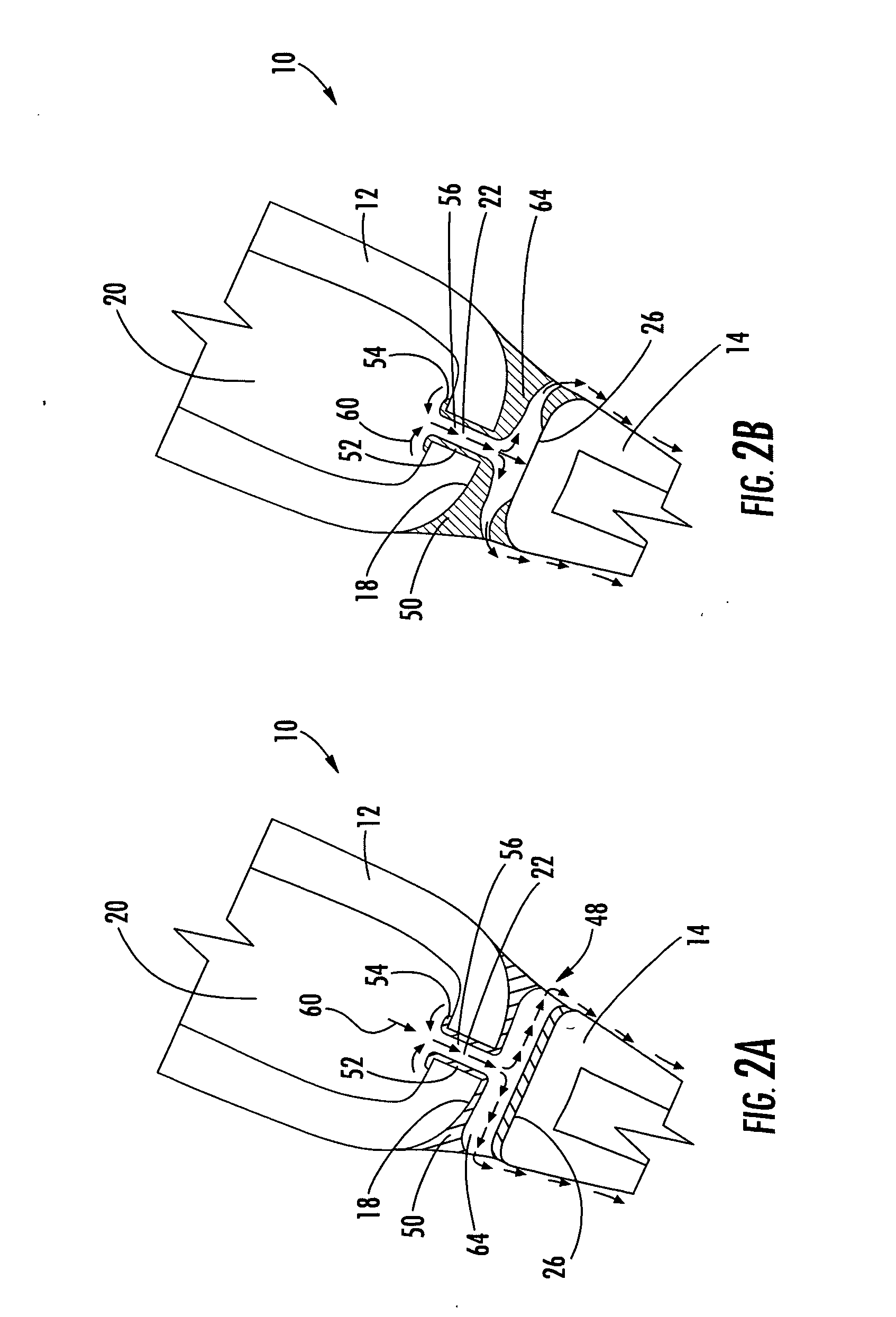
[0023] Embodiments of the present invention provide a vane construction that facilitates the selective incorporation of different materials in a turbine vane, particularly a vane with a separate metal trailing edge piece. Embodiments of the invention will be explained in the context of two possible vane assemblies, but the detailed description is intended only as exemplary. Embodiments of the invention are shown in FIGS. 1-9, but the present invention is not limited to the illustrated structure or application.

[0024] There are several material systems that can be beneficial to certain portions of a turbine vane. For example, ceramic matrix composites (CMC) are desirable because of their low thermal conductivity characteristics. When covered with a thermal insulating material, a CMC vane can be cooled with a minimal amount of cooling air because of their low heat transfer coefficients combined with their high temperature capability. The thermal insulating material can be a friable gr...


PUM

PropertyMeasurementUnit
bending forcesaaaaaaaaaa
thermal expansionaaaaaaaaaa
temperatureaaaaaaaaaa

Abstract

Embodiments of the invention relate to a vane assembly formed by a forward airfoil segment and an aft airfoil segment. The aft segment is made of metal and can define the trailing edge of the vane assembly. The forward segment can be made of ceramic, CMC or metal. The forward and aft segments cannot be directly joined to each other because of differences in their rates of thermal expansion and contraction. The forward and aft segments can be positioned substantially proximate to each other so as to form a gap therebetween. In one embodiment, the gap can be substantially sealed by providing a coupling insert or leaf springs in the gap. A separate metal aft segment can take advantage of the beneficial thermal properties of the metal to improve cooling efficiency at the trailing edge without limiting the rest of the vane to being made out of metal.

Description

FIELD OF THE INVENTION [0001] The invention relates in general to turbine engines and, more particularly, to turbine vanes. BACKGROUND OF THE INVENTION [0002] During the operation of a turbine engine, turbine vanes, among other components, are subjected to high temperature combustion gases. The vanes can be made of any of a number of materials, and each material can provide certain advantages in managing the thermal loads imposed on the vane. However, at least from a thermal design standpoint, experience has demonstrated that no single material is ideal for every portion of the vane. Thus, there is a need for a vane construction that can facilitate the selective incorporation of dissimilar materials in a turbine vane. SUMMARY OF THE INVENTION [0003] In one respect, aspects of the invention relate to an airfoil assembly. The airfoil assembly includes a forward airfoil segment and an aft airfoil segment. The forward airfoil segment defines the leading edge of the airfoil assembly. The...

Claims


Application Information

Patent Timeline
Patent Type & Authority Applications(United States)
IPC IPC(8): B64C3/00B64C21/04
CPCF01D5/146F01D5/147F05D2240/301F05D2300/603F05D2260/20F05D2260/221F05D2300/21F05D2240/57
Inventor CAMPBELL, CHRISTIAN X.
Owner SIEMENS ENERGY INC
Why Eureka
Try Eureka