Plasma radiation source

a radiation source and plasma technology, applied in the direction of x-ray apparatus, nuclear engineering, electrical apparatus, etc., can solve the problems of running counter to optimized conversion efficiency, affecting the efficiency of radiation transmission, and insufficient elimination of disadvantages, so as to reduce the burden of gas

Inactive Publication Date: 2006-10-12
XTREME TECH
View PDF1 Cites 51 Cited by
  • Summary
  • Abstract
  • Description
  • Claims
  • Application Information

AI Technical Summary

Benefits of technology

[0014] The substantial advantage of the invention consists in that fast particles exiting the plasma are decelerated and thermalized in a surrounding region of the plasma essential for the function of the radiation source as a result of the enclosure of the target flow and, in particular, of the radiation-emitting plasma. As a result, not only are the collimating optics protected against direct damage from the fast particles, but also a release of material within the radiation source resulting from erosion caused by the fast particles moving in all directions can be prevented. Otherwise, vaporized material would precipitate on functional elements inside the radiation source due to condensation and would lead to mirror-dullness of the collimating optics.
[0015] In a particular embodiment of the invention, a nozzle arrangement is provided which forms the gas inlet and is distributed around a center, the target nozzle being directed into the nozzle arrangement, and the nozzle arrangement generates partial gas flows which at least partly enclose the target flow and the radiation-emitting plasma by mutual overlapping.
[0016] In an advantageous embodiment, the nozzle arrangement can be constructed as a Laval nozzle arrangement which generates the partial gas flows as supersonic gas flows.
[0017] By means of the overlapping, directed partial gas flows, a solid angle determined by the arrangement of the partial gas flows can be completely protected from the plasma by limiting the propagation of debris to the extent that harmful effects on the collimating optics and other component parts of the radiation source are prevented. Slightly elliptic jet cross sections which can be made to overlap effectively as round cross sections are especially advantageous.
[0018] Based on the steps according to the invention, the absorption of the generated radiation by the gas used for debris reduction can be kept low because the gas flows are in close proximity to the target flow and the plasma so that large portions of the radiation reflected by the collimating optics are directed past the columnar gas flow due to the divergence. In this way, the gas burden is reduced by the invention compared to known technical solutions.
[0019] The invention will be described more fully in the following with reference to the schematic drawing.

Problems solved by technology

The latter is important because debris can exert a harmful influence on optical components performing beam-shaping functions for utilization of the radiation.
On the one hand, the radiation sources can be conceived in such a way through the type of plasma excitation, the design of the plasma environment and the choice of the material composition of the plasma that as little debris as possible is generated; but this often runs counter to optimized conversion efficiency.
However, this disadvantage is not adequately eliminated.
A further drawback consists in that secondary sputtering is not countered.

Method used


Image

  • Plasma radiation source
  • Plasma radiation source
  • Plasma radiation source

Examples


Embodiment Construction

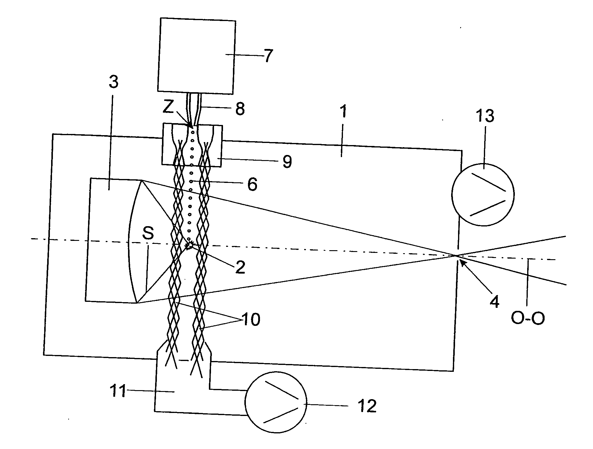
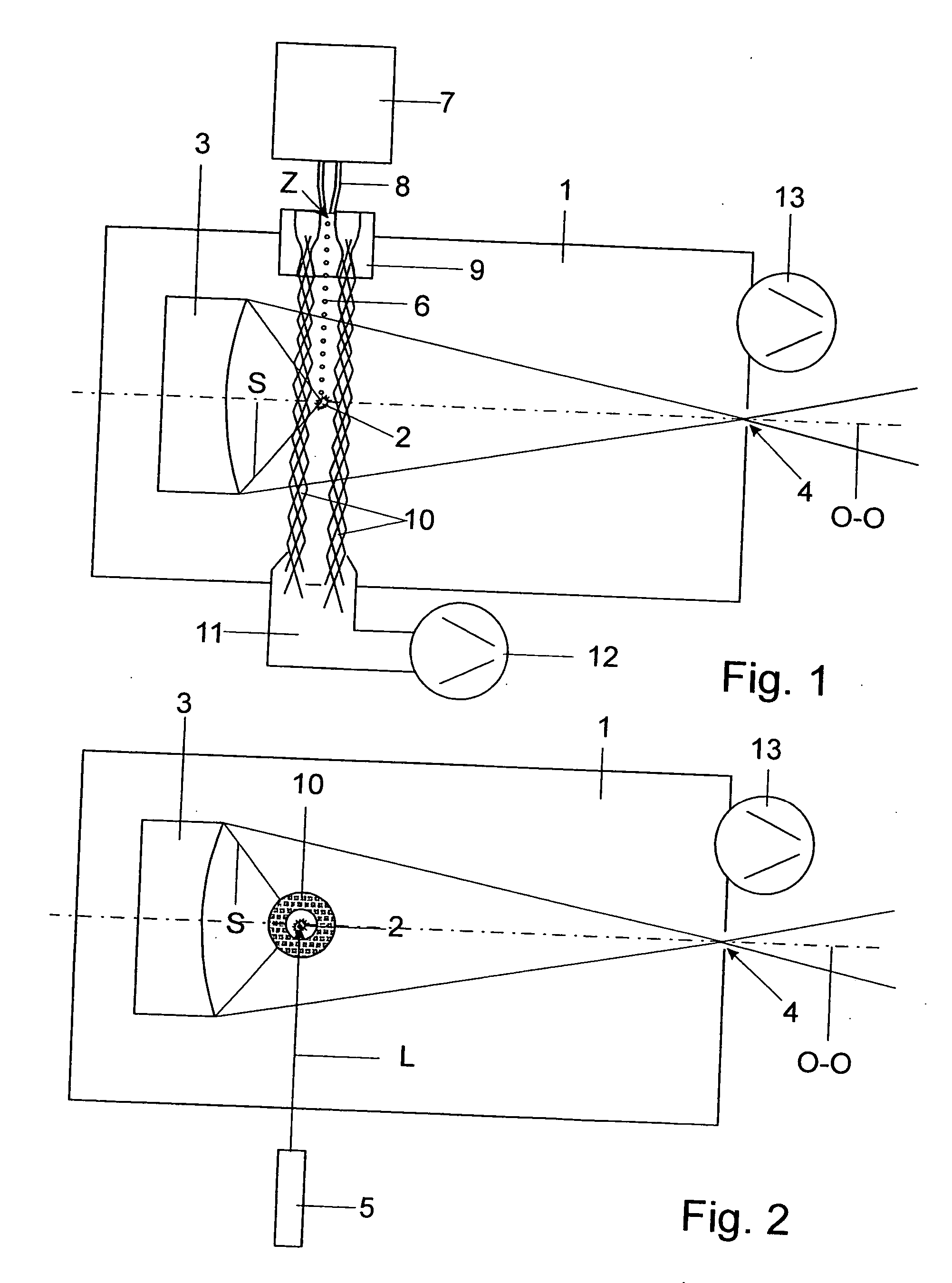
[0025] The plasma radiation source shown in FIGS. 1 and 2 contains, in a vacuum chamber 1, a plasma 2 which is induced by laser radiation. The radiation S emitted by the plasma 2 is directed to a radiation outlet opening 4 in the vacuum chamber 1 by means of an optical element which is arranged in the vacuum chamber 1 and constructed as a collector mirror 3. An intermediate focus is generated by imaging the plasma 2 with the collector mirror 3, this intermediate focus being localized in, or in the vicinity of, the radiation outlet opening 4 and serving as an interface to exposure optics in a semiconductor exposure installation for which the plasma radiation source, preferably designed for the EUV wavelength region, is provided.

[0026] The laser radiation L generated by a laser 5 is directed preferably perpendicular to a target flow 6 for the generation of plasma as excitation radiation, this target flow 6 advantageously being supplied by a target generator 7 via a target nozzle 8, e...


PUM


Abstract

The object of a plasma radiation source is to ensure a more effective protection against debris and, in particular, to counteract secondary sputtering. A target flow that is provided by a target generator by means of a target nozzle and a plasma that is generated by a pulsed excitation beam are enclosed within a vacuum chamber by a gas flow directed transverse to the optical axis.

Description

CROSS-REFERENCE TO RELATED APPLICATION [0001] This application claims priority of German Application No. 10 2005 017 263.6, filed Apr. 12, 2005, the complete disclosure of which is hereby incorporated by reference. BACKGROUND OF THE INVENTION [0002] a) Field of the Invention [0003] The invention is directed to a plasma radiation source containing a target generator with a target nozzle for the metering and orientation of a target flow for plasma generation and a vacuum chamber in which a pulsed excitation beam is directed to the target flow in order to generate a radiation-emitting plasma whose radiation is directed from at least one optical element to a radiation outlet opening in the vacuum chamber and which has a gas inlet and a gas outlet for a gas flow serving as debris protection. [0004] b) Description of the Related Art [0005] Lithography in extreme ultraviolet requires radiation sources with sufficiently intensive radiation and a low debris burden. The latter is important be...

Claims


Application Information

Patent Timeline
Patent Type & Authority Applications(United States)
IPC IPC(8): G21G4/00
CPCH05G2/006H05G2/003
Inventor HERGENHAN, GUIDOGAEBEL, KAIBRAUNER, THOMAS
Owner XTREME TECH
Why Eureka
Try Eureka