Air spring assembly and method

Inactive Publication Date: 2006-10-12
FIRESTONE IND PROD COMPANY
View PDF13 Cites 80 Cited by
  • Summary
  • Abstract
  • Description
  • Claims
  • Application Information

AI Technical Summary

Benefits of technology

[0012] Accordingly, an improved air spring assembly and method

Problems solved by technology

Additionally, it is well understood that air springs are commonly exposed to harsh environments, such as in vehicle suspension applications in which water, dirt, salt and other materials are present.
There are, however, numerous disadvantages associated with manufacturing a piston from a plastic material.
One disadvantage is that air spring piston applications typically require high performance plastic materials.
Accordingly, specialty plastics are normally considerably more expensive than common commodity grades.
Therefore, the cost associated with the manufacture of larger pistons can significantly increase due, at least in part, to the increased expenses of the additional quantity of the plastic material.
As such, at some point it becomes less expensive to use metal and incur the associated assembly costs.
Another disadvantage of manufacturing pistons from a plastic material is associated with the method of manufacturing the parts.
The injection molding process imposes certain design constraints on the configuration of the parts being produced.
In practice, this is a real constraint that limits the options available in designing the part or component.
Otherwise, this piece of the mold tooling will either damage the part when the mold halve

Method used


Image

  • Air spring assembly and method
  • Air spring assembly and method
  • Air spring assembly and method

Examples


Embodiment Construction

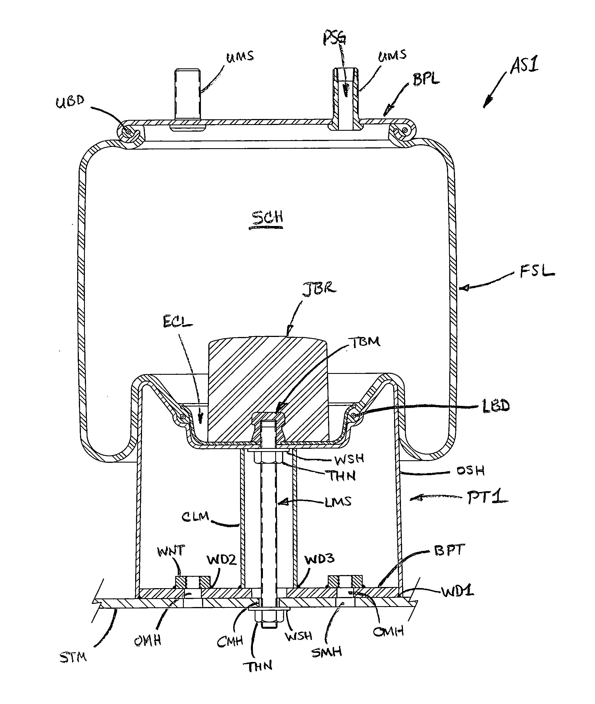
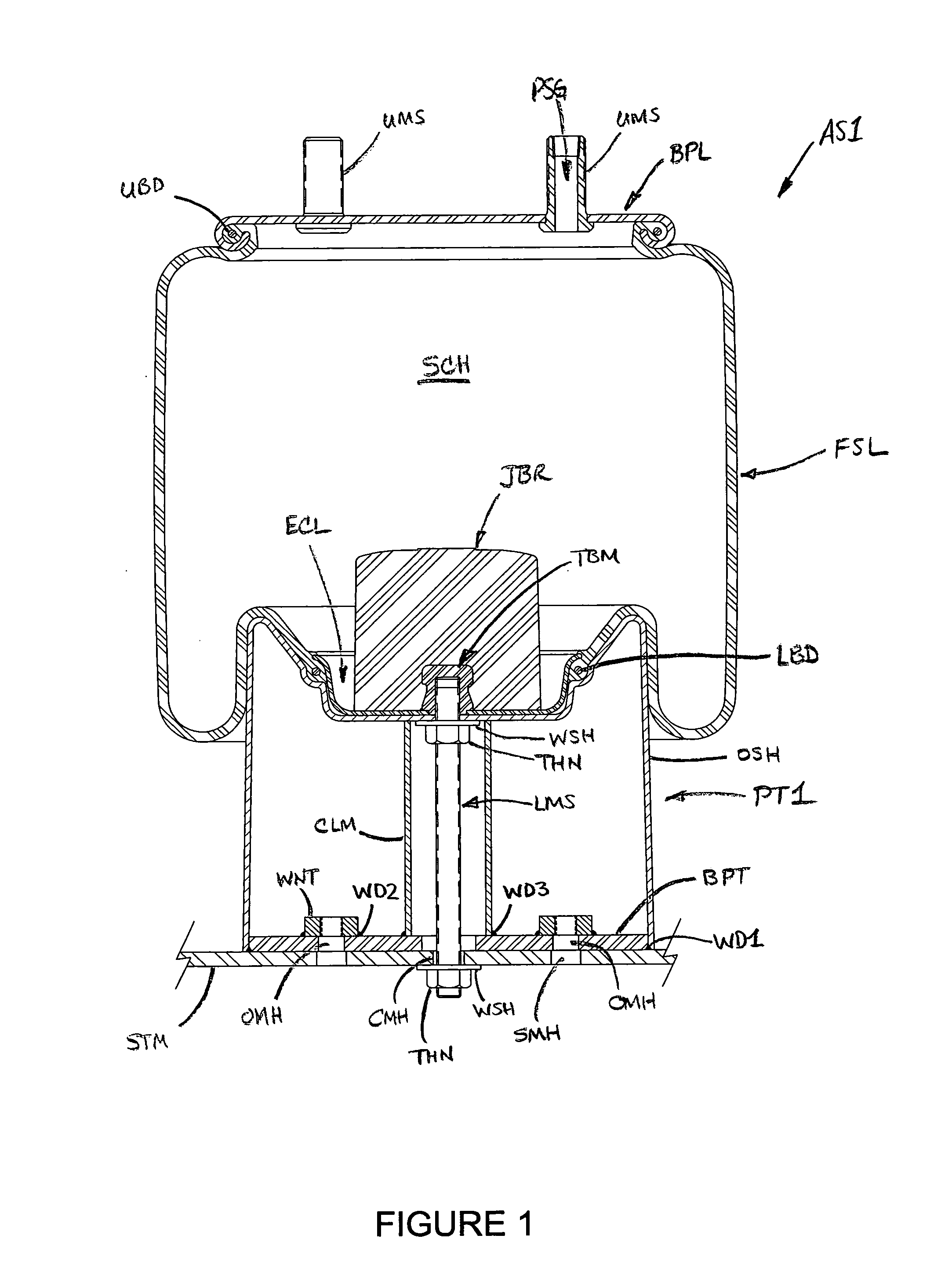
[0043]FIG. 1 illustrates an air spring AS1 of a generally known construction secured along a structural member STM, such as a component of a vehicle, for example. Air spring AS1 includes a top or bead plate BPL and a piston PT1 in spaced relation thereto. A flexible sleeve FSL is secured between the bead plate and piston and generally defines a spring chamber SCH formed therebetween.

[0044] Flexible sleeve FSL includes an upper mounting bead UBD that is captured by bead plate BPL in a typical manner, such as by crimping the peripheral edge of the bead plate around the upper mounting bead. Upper mounting studs UMS are supported on bead plate BPL and project outwardly therefrom. An air passage PSG extends through one of the upper mounting studs and is in fluid communication with spring chamber SCH.

[0045] Flexible sleeve FSL also includes a lower mounting bead LBD that is secured on piston PT1 using an end closure ECL. A threaded bumper mount TBM receives a lower mounting stud LMS tha...


PUM


Abstract

A piston assembly for an air spring includes an outer shell and a structural insert. The outer shell includes a side wall and an end wall at least partially defining a shell cavity having an open end. The structural insert is received in the shell cavity and includes a central portion and a plurality of support walls extending outwardly from the central portion toward the side wall of the outer shell. The central portion includes first and second opposing ends with the first end disposed toward the end wall of the outer shell and the second end disposed toward the open end of the outer shell. An air spring assembly includes such a piston assembly. A method of manufacturing an air spring assembly is also included.

Description

[0001] This application claims priority from U.S. Provisional Patent Application No. 60 / 669,715 filed on Apr. 7, 2005, which is hereby incorporated herein by reference in its entirety.BACKGROUND [0002] The present novel concept broadly relates to fluid suspension systems and, more particularly, to an air spring assembly having an improved piston construction and a method of manufacturing the same. [0003] It is to be specifically understood that the subject novel concept is capable of broad use in a wide variety of suitable applications and environments and can be used in association with air spring assemblies of any suitable size, type and / or configuration without departing from the principles thereof. [0004] One category of known air spring assemblies, referred to in the art as rolling lobe-type air springs, typically includes a top plate, a piston and a flexible sleeve secured therebetween. The flexible sleeve forms a lobe that rolls up and down an outer side wall of the piston in...

Claims


Application Information

Patent Timeline
IPC IPC(8): F16F9/04
CPCB60G11/28B60G2202/152F16F9/057B60G2204/4502B60G2206/424B60G2204/126
Inventor LEVY, DANIEL I.
Owner FIRESTONE IND PROD COMPANY
Why Eureka
Try Eureka