Ball coax interconnect

a technology of interconnection and ball coax, which is applied in the direction of waveguides, waveguide type devices, multiple-port networks, etc., can solve the problems of not meeting the specific needs of high-frequency integrated optical-electronic assemblies, conventional packaging technologies, including bga packages, and failing to provide interconnections which would allow high-frequency electrical processing

Inactive Publication Date: 2006-10-12
CORNING INC
View PDF9 Cites 36 Cited by
  • Summary
  • Abstract
  • Description
  • Claims
  • Application Information

AI Technical Summary

Problems solved by technology

Moreover, since BGA packages do not include peripheral leads, BGA packages take up less room on a printed circuit board, and may be closely spaced.
Conventional packaging technologies, including BGA packages, however, fail to address the specific needs of high frequency integrated optical-electronic assemblies, particularly with respect to providing low loss, reproducible electrical interconnections at the circuit board level for mounting high frequency optical-electronic assemblies.
Specifically, known packaging techniques fail to provide t

Method used


Image

  • Ball coax interconnect
  • Ball coax interconnect
  • Ball coax interconnect

Examples


example 1

[0089] Referring to FIGS. 13-16, the initial High Frequency 3D Electromagnetic Simulation Software (HFSS™) simulations for a Low Temperature Co-fired Ceramic (LTCC) substrate—BGA coaxial interface of the improved structure are shown.

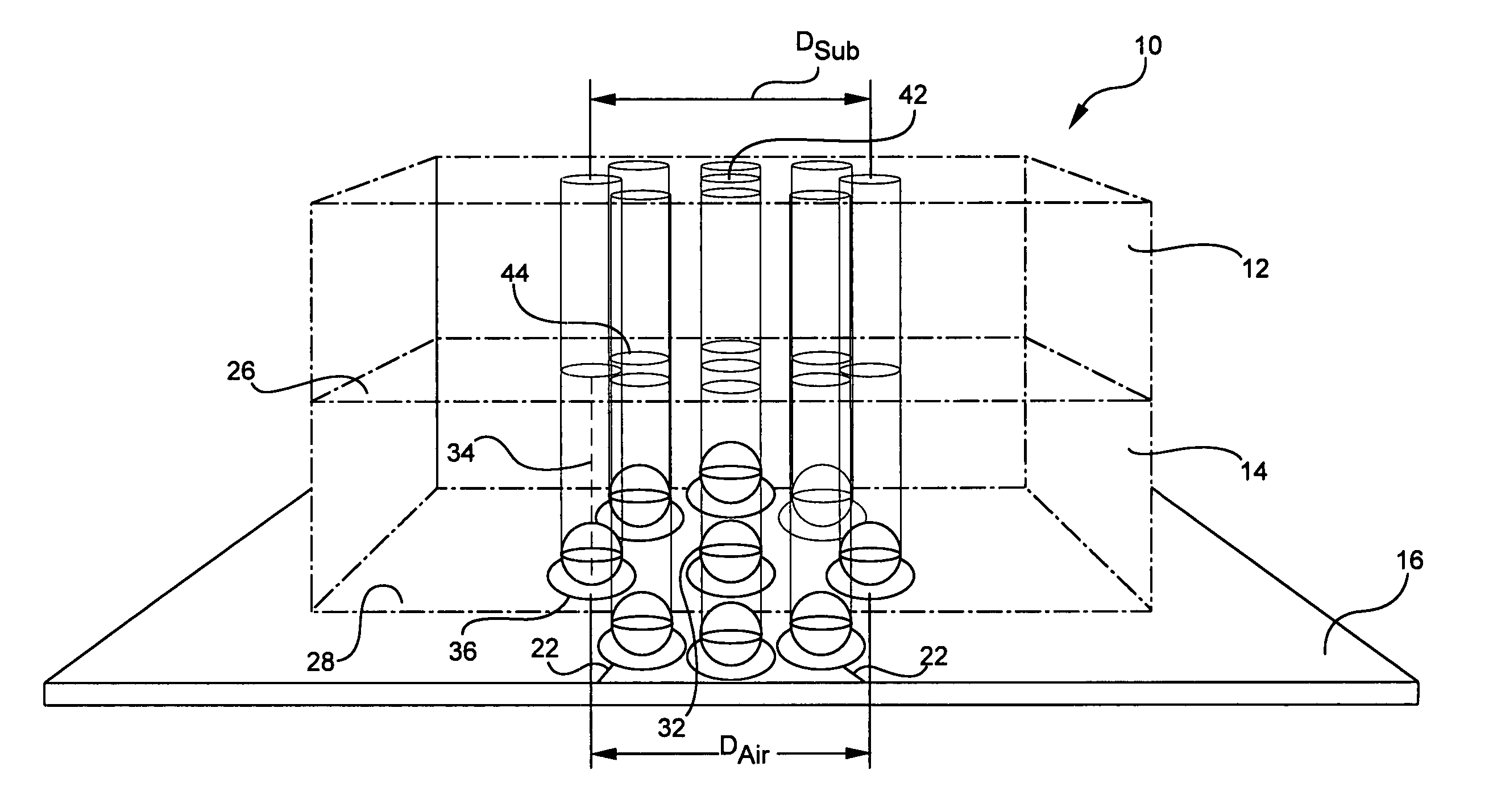
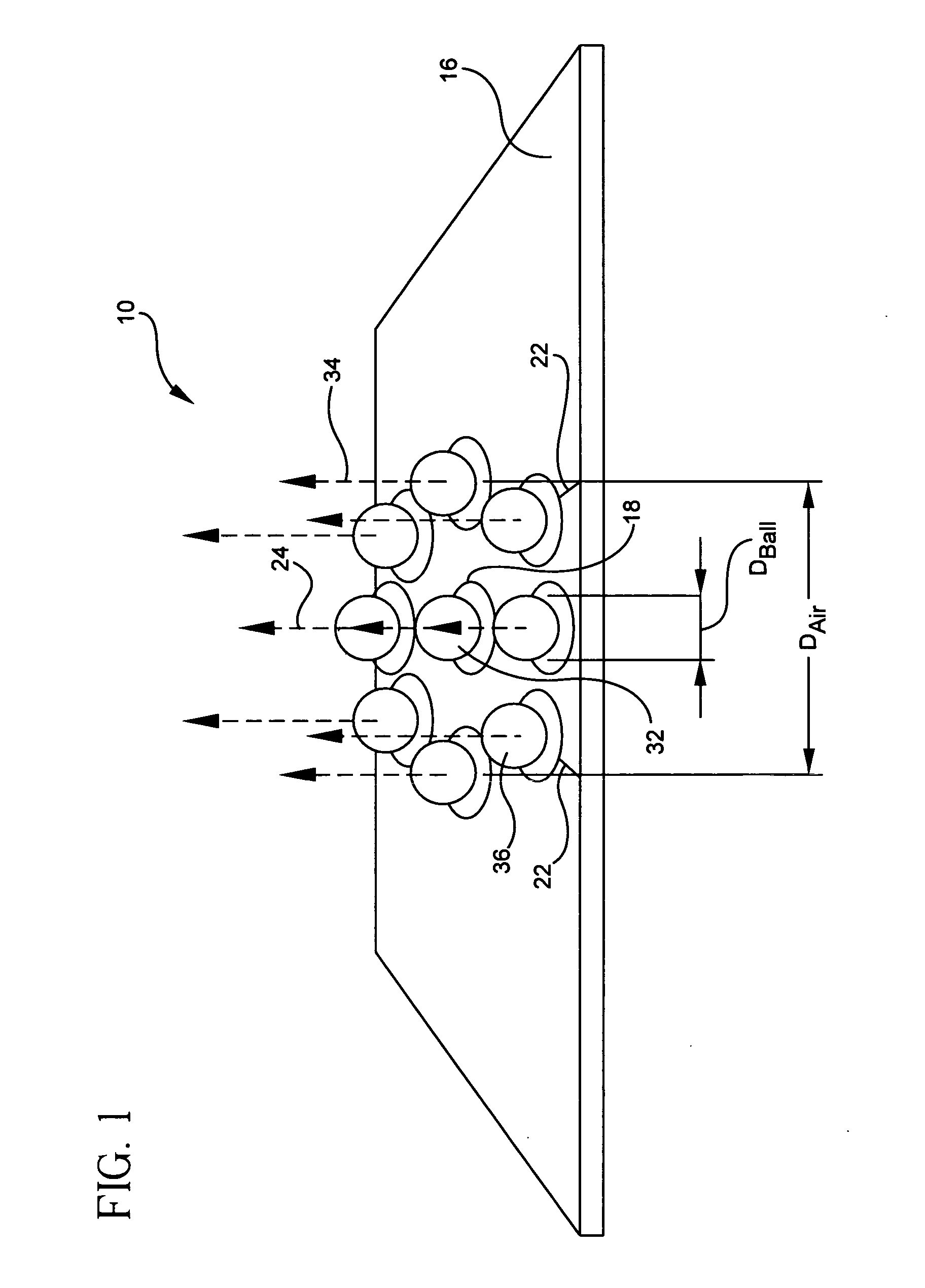
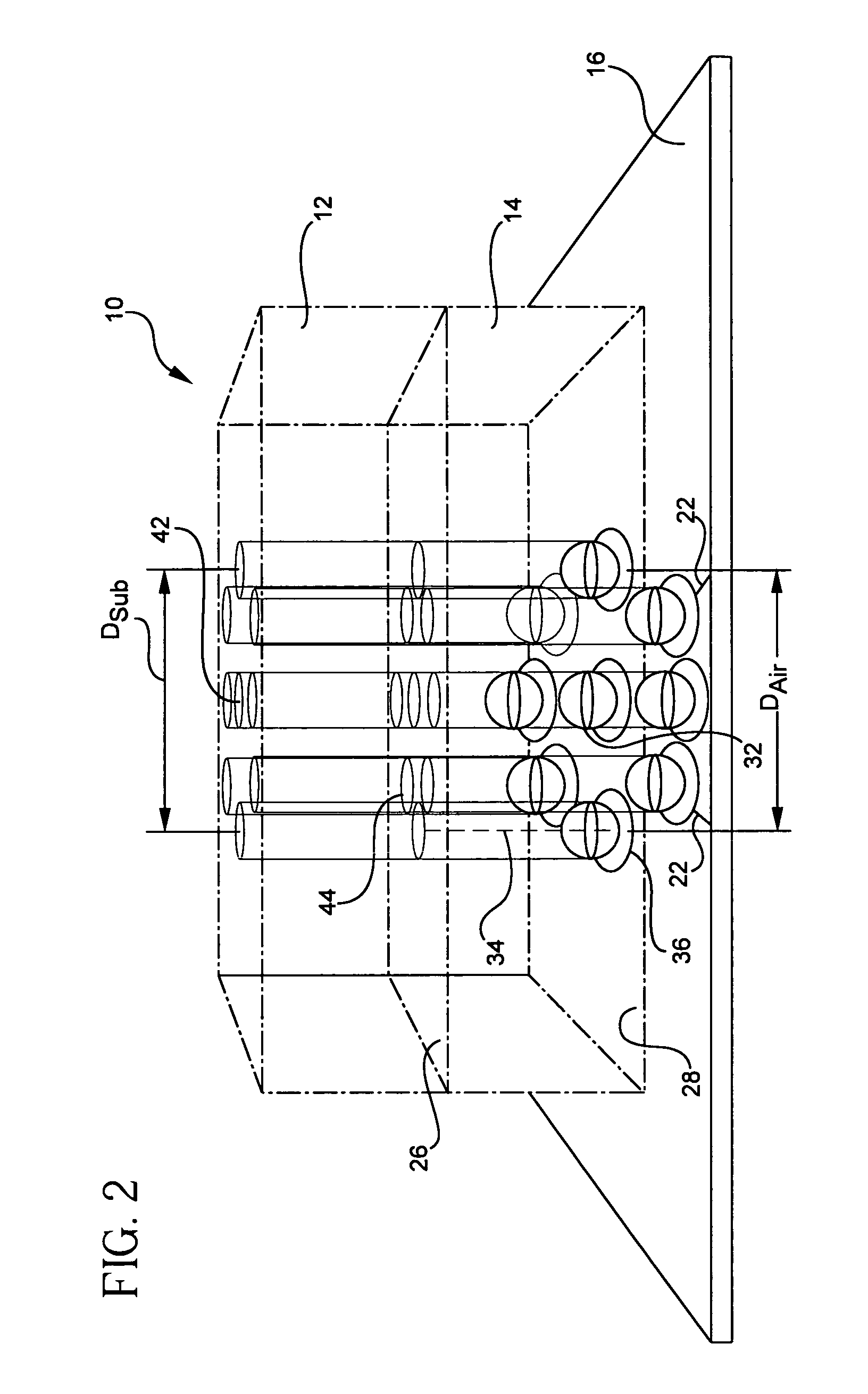
[0090] Referring to FIG. 13, a 3D schematic of the inventive circular ball coax design is represented with the HFSS™ model containing a three layer structure. The bottom and top layers 12 and 66 are LTCC, and the middle layer 134 is air. Cylinders are plated through or filled hole vias 42 and 44, balls 442 and 444 are BGA balls. Wave injection ports are on the top and bottom (Z=0 and 2.5 mm) and are normal to the direction of wave propagation in the Z axis. The LTCC substrate thicknesses are 1 mm (independent of design) and the thickness of the air substrate is 0.5 mm. The balls sit slightly inside the LTCC vias, 0.05 mm on top and bottom.

[0091] Referring to FIG. 14, the HFSS™ modeling results of the reflection coefficient with the parameters of FIG. 1...


PUM


Abstract

A pseudo-coaxial vertical transition (10) includes a substrate (16). A bump array is disposed in a substantially concentric bump pattern upon the substrate (16) for simulating a pseudo-coaxial vertical electromagnetic wave propagation. The bump array is formed from a centrally disposed bump (32) having a predetermined bump diameter, and a plurality of at least five ground bumps (36) substantially equi-distant and circularly disposed about the centrally disposed bump (32). The predetermined bump diameter and a bump spacing of the centrally disposed bump are determined in relation to the plurality of ground bumps and a dielectric constant of air for providing a characteristic impedance.

Description

BACKGROUND OF THE INVENTION [0001] 1. Field of the Invention [0002] The present invention relates generally to interconnection devices, and particularly to interconnection devices for mounting high-speed or high-frequency optical-electronic multi-layered assemblies to circuit boards. [0003] 2. Technical Background [0004] Rapid advances in technology have accelerated the need for packaging devices which can accommodate, among other factors, connection requirements, higher operating frequencies, such as around 40 GHz, and increases in the numbers of inputs and outputs on integrated circuits (ICs) for optical and electronic circuits. Conventional packaging devices include ball grid arrays (BGA), wire bonding, tape automated bonding (TAB), quad flat packs (QFP) and controlled collapse chip connections (C4 or flip chip). BGA packages tend to be particularly popular because they are easier to surface mount on a printed circuit board than fine pitch peripheral lead packages, such as QFPs. ...

Claims


Application Information

Patent Timeline
IPC IPC(8): H01P5/02H01P1/00
CPCH01L2223/6622H05K1/0222H05K1/025H01P3/06H05K2201/09618H05K2201/09809H01P5/085H05K3/3436
Inventor HENNING, LARRY C.HUGHES, LAWRENCE C. JR.MATTHEWS, KAREN I.NAIR, DEEPUKUMAR M.
Owner CORNING INC
Why Eureka
Try Eureka