

Ink cartridge
- Summary
- Abstract
- Description
- Claims
- Application Information
AI Technical Summary
Benefits of technology
Problems solved by technology
Method used
Image

Examples
Embodiment Construction
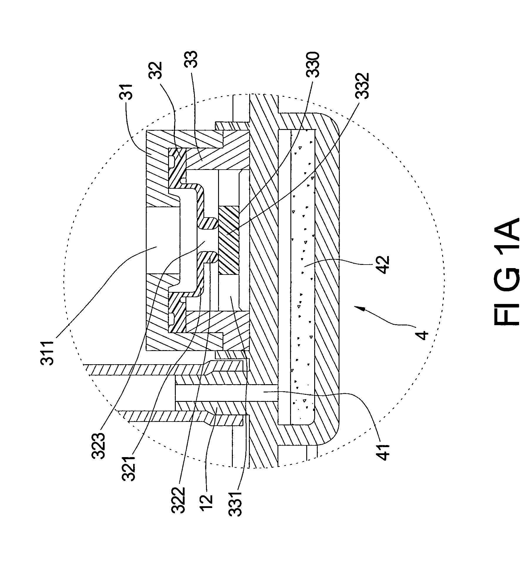
[0015] There is a permeable membrane attached on the lower surface of the pressure regulator. When the ink is drawn out of the printhead, the equivalent air would be drawn from the pressure regulator to balance the negative pressure within the ink cartridge thru the atmosphere directly. For security, additional parts will be added to improve the ink leakage problem according to the present invention.
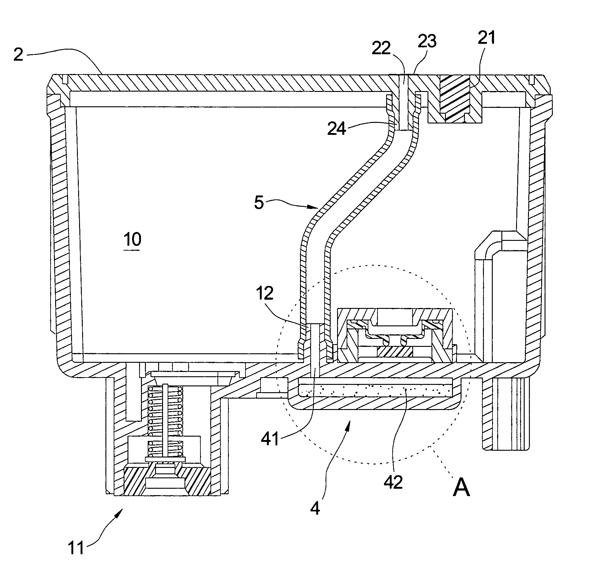
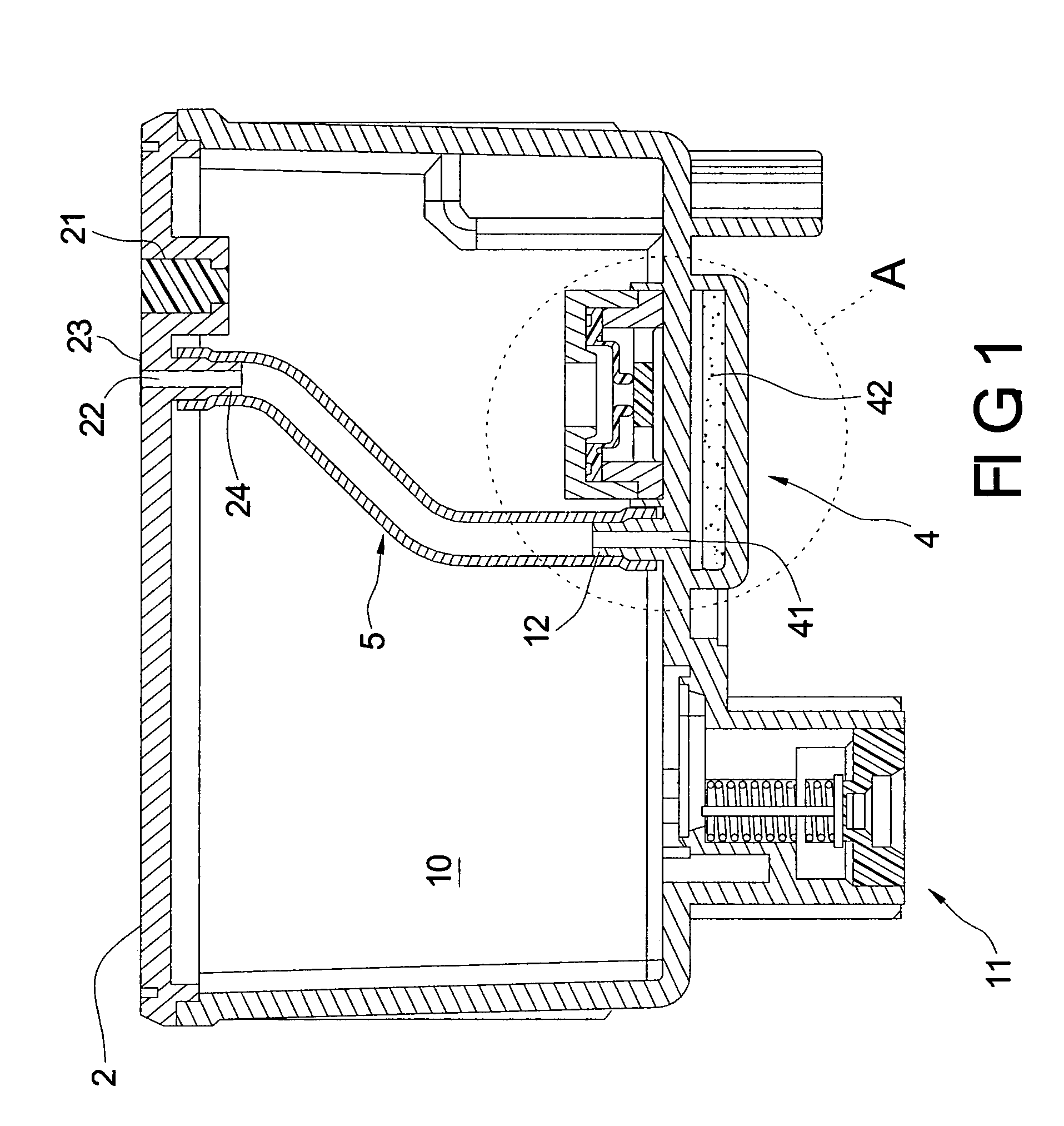
[0016] Referring to FIG. 1, an ink cartridge of a first embodiment according to the present invention includes a hollow ink tank body 1, a cover member 2 connected to the hollow ink tank body 1, a pressure regulator 3 mounted to a bottom of the hollow ink tank body 1, a tank 4 disposed under the hollow ink tank body 1 and connected to a bottom thereof, and a hollow tube 5 communicating with the atmosphere and the tank 4 via a venthole 41 that is formed to communicated with the tank 4 and the hollow ink tank body 1. The hollow ink tank body 1 defines a cavity 10 therein for fill with ink...
PUM
 Abstract
Description
Claims
Application Information